background image

Page 1

©

 2012 Lennox Industries Inc.

Litho U.S.A.

Corp. 1102−L1

EL195DF

Service Literature

Revised 02/2012

EL195DF SERIES UNITS

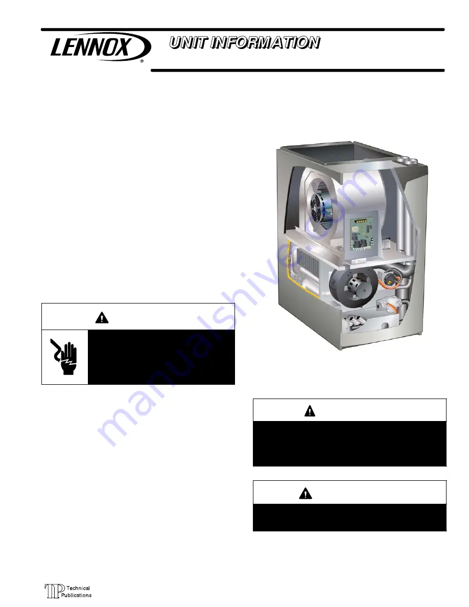
EL195DF series units are high−efficiency gas furnaces
manufactured with Lennox DuralokPlus

t

 aluminized

steel clamshell−type heat exchangers, with a stainless steel
condensing coil. EL195DF units are available in heating
input capacities of 44,000 to 110,000 Btuh (13 to 32.2 kW)
and cooling applications from 2 through 5 tons (7.0 through
17.6 kW). Refer to Engineering Handbook for proper sizing.

Units are factory equipped for use with natural gas. A kit is
available for conversion to LP/Propane operation. All
EL195DF units are equipped with a  hot surface ignition
system. The gas valve is redundant to assure safety
shut−off as required by C.S.A.

The heat exchanger, burners and manifold assembly can be
removed for inspection and service. The maintenance section

gives a detailed description on how this is done.

 All specifications are subject to change. Procedures outlined
in this manual are presented as a recommendation only
and do not supersede or replace local or state codes.


WARNING

Electric shock hazard. Can cause injury
or death. Before attempting to perform
any service or maintenance, turn the
electrical power to unit OFF at discon-
nect switch(es). Unit may have multiple
power supplies.

Table of Contents

Specifications

2

. . . . . . . . . . . . . . . . . . . . . . . . . . . . . . . . . 

Optional Accessories

3

. . . . . . . . . . . . . . . . . . . . . . . . . . 

Blower Performance Data

4

. . . . . . . . . . . . . . . . . . . . . . 

I−Unit Components

6

. . . . . . . . . . . . . . . . . . . . . . . . . . . . . 

II Placement and Installation

16

. . . . . . . . . . . . . . . . . . . . 

III−Start−Up

36

. . . . . . . . . . . . . . . . . . . . . . . . . . . . . . . . . . . 

IV−Heating System Service Checks

37

. . . . . . . . . . . . . . 

V−Typical Operating Conditions

40

. . . . . . . . . . . . . . . . . . 

VI−Maintenance

41

. . . . . . . . . . . . . . . . . . . . . . . . . . . . . . . 

VII−Wiring and Sequence of Operation

43

. . . . . . . . . . . . 

VIII−Troubleshooting

44

. . . . . . . . . . . . . . . . . . . . . . . . . . . 

WARNING

Improper installation, adjustment, alteration, service
or maintenance can cause property damage, person-
al injury or loss of life. Installation and service must
be performed by a licensed professional installer (or
equivalent), service agency or the gas supplier.

WARNING

Sharp edges.
Be careful when servicing unit to avoid sharp edges
which may result in personal injury.

Содержание EL195DF SERIES

Страница 1: ...ed description on how this is done All specifications are subject to change Procedures outlined in this manual are presented as a recommendation only and do not supersede or replace local or state cod...

Страница 2: ...x 1 2 Mipt 1 2 slip x 1 2 Mipt with field supplied PVC coupling o d 1 2 slip x 1 2 Npt 1 2 slip x 1 2 Npt 1 2 slip x 1 2 Npt 1 2 slip x 1 2 Npt Indoor Blower Wheel nom dia x width in 10 x 8 11 1 2 x...

Страница 3: ...Mount 2 2 1 2 or 3 in 51W11 51W11 Wall Close Couple US 2 in 22G44 3 in 44J40 44J40 Wall Close Couple WTK Canada 2 in 30G28 3 in 81J20 81J20 Termination Kits Direct or Non Direct vent Roof 2 in 15F75 1...

Страница 4: ...1070 1730 765 1640 650 1515 550 0 80 1735 1030 1620 740 1590 620 1415 535 0 90 1640 1010 1535 715 1480 600 1330 510 EL195DF045P36B PERFORMANCE Less Filter External Static Pressure in w g Air Volume W...

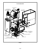
Страница 5: ...shipping location BLOWER MOTOR hidden OUTER ACCESS PANEL COMBUSTION AIR INDUCER BURNER BOX ASSEMBLY includes sensor rollout switches and ignitor GAS VALVE BLOWER DECK COLD END HEADER BOX PRIMARY LIMI...

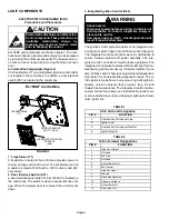
Страница 6: ...2 WARNING Shock hazard Disconnect power before servicing Control is not field repairable If control is inoperable simply re place entire control Can cause injury or death Unsafe operation will result...

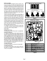
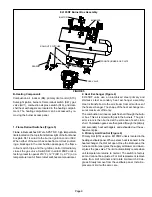
Страница 7: ...y The heating fan on time of 30 seconds is not adjustable Heating Fan Off Delay The heat fan off delay amount of time that the blower oper ates after the heat demand has been satisfied may be ad juste...

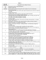
Страница 8: ...heck for restriction in vent pipe combustion air inlet and heat exchanger Determine cause of restriction before placing furnace back inoperation 9 Pressure Switch failed to close or opened during heat...

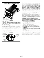
Страница 9: ...s are manual reset 2 Heat Exchanger Figure 6 EL195DF units use an aluminized steel primary and stainless steel secondary heat exchanger assembly Heat is transferred to the air stream from all surfaces...

Страница 10: ...e The ignition control allows the gas valve to remain open as long as flame signal is sensed NOTE The EL195DF is polarity sensitive Make sure that the furnace is wired correctly and is properly ground...

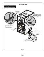
Страница 11: ...Multi Meter Red Collar Indicates To Control Sensor Terminal T o Flame Terminal Remove Sensor Wire from Intergrated Control and Connect Alligator Clip to Terminal on Control Flame Sensor Terminal Flam...

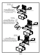
Страница 12: ...e between 39 and 70 ohms If the reading is correct then the problem is with the wiring between the jack plug and the control If reading is not correct the issue is the ignitor Integrated Control Detai...

Страница 13: ...r flow through the heat exchanger The switch is a SPST N O prove switch electrically con nected to the integrated control The purpose of the switch is to prevent burner operation if the combustion air...

Страница 14: ...rential The pressure differential should be greater than those listed in table 5 5 Remove thermostat demand and allow to cycle off 6 Remove manometer and tee s Reinstall combustion air sensing hoses t...

Страница 15: ...h Check the differential pressure across the pressure switch Check for restricted inlet vent Remove all blockage Check for proper vent sizing and run length See table 10 Wrong pressure switch installe...

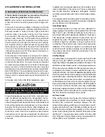
Страница 16: ...n addition to providing combustion air fresh outdoor air di lutes contaminants in the indoor air These contaminants may include bleaches adhesives detergents solvents and other contaminants which can...

Страница 17: ...ought in for combustion and ventila tion the confined space must have two permanent open ings One opening shall be within 12 inches 305 mm of the top of the enclosure and one opening within 12 inches...

Страница 18: ...ipe F441 Schedule 40 CPVC Fittings F438 SDR 21 PVC or SDR 26 PVC Pipe D2241 SDR 21 CPVC or SDR 26 CPVC Pipe F442 Schedule 40 ABS Cellular Core DWV Pipe F628 Schedule 40 ABS Pipe D1527 Schedule 40 ABS...

Страница 19: ...YES YES YES 5YES YES YES 110 2 YES YES YES 5YES YES YES 2 1 2 YES YES 5YES YES YES 3 YES YES 5YES YES YES 135 3 YES YES 5YES YES NOTE Standard Terminations do not include any vent pipe or elbows exter...

Страница 20: ...ement forcefully insert end of pipe into socket until it bottoms out Turn PVC pipe 1 4 turn dur ing assembly but not after pipe is fully inserted to dis tribute cement evenly DO NOT turn ABS or cellul...

Страница 21: ...ws or 10 ft plus 1 elbow Any approved termination may be added to the minimum length listed Regardless of the diameter of pipe used the standard roof and wall terminations described in section Exhaust...

Страница 22: ...56 34 n a 105 105 83 48 128 127 108 108 4 66 51 29 n a 100 100 78 43 123 122 103 103 5 61 46 24 n a 95 95 73 38 118 117 98 98 6 56 41 19 n a 90 90 68 33 113 112 93 93 7 51 36 14 n a 85 85 63 28 108 1...

Страница 23: ...transitioning up in pipe size use the shortest length of 2 PVC pipe possible NOTE Exhaust pipe and intake pipe must be the same diameter 2 FIGURE 21 TYPICAL INTAKE PIPE CONNECTIONS 2 2 TRANSITION 2 3...

Страница 24: ...In both Non Direct Vent and Direct Vent applications the vent termination is limited by local building codes In the absence of local codes refer to the current National Fuel Gas Code ANSI Z223 1 NFPA...

Страница 25: ...ly inlet Clearance above paved sidewalk or paved driveway located on public property Clearance under veranda porch deck or balcony 12 Equal to or greater than soffit depth 3 feet 9m 12 3 feet 9m withi...

Страница 26: ...ove paved sidewalk or paved driveway located on public property Clearance under veranda porch deck or balcony 12 7 feet 2 1m 3 feet 9m within a height 15 feet 4 5m above the meter regulator assembly 3...

Страница 27: ...Pipe Size Termination Pipe Size 045 and 070 2 51mm 2 1 2 64mm 3 76mm 1 1 2 38mm 090 2 51mm 110 2 51mm EL195DF 045 070 and 090 units with the flush mount termination must use the 1 1 2 accelerator sup...

Страница 28: ...n tee The accelerator is not required 2 As required Flue gas may be acidic and may adversely affect some building materials If a side wall vent termination is used and flue gases will impinge on the b...

Страница 29: ...A D WALL SUPPORT 1 2 13mm ARMAFLEX INSULATION IN UNCONDITIONED SPACE E EXTENDED APPLICATION A FIGURE 29 FIELD FABRICATED WALL TERMINATION OR 15F74 WALL RING TERMINATION KIT With INTAKE ELBOW See vent...

Страница 30: ...r provided on 71M80 44W92 kits for EL195DF045P36B 070P36B FIGURE 32 EXHAUST VENT INTAKE AIR 5 1 2 140mm Front View 12 305mm 5 127mm 18 MAX 457mm EXHAUST VENT INTAKE AIR OPTIONAL VENT TERMINATION FOR M...

Страница 31: ...an 12 in 305 mm above snow accumulation or other obstructions field fabricated piping must be installed FIGURE 36 12 305 mm Minimum Above Grade or Average Snow Accumulation 1 2 13 mm FOAM INSULATION F...

Страница 32: ...xhaust piping must terminate straight out or up as shown The termination pipe must be sized as listed in table 11 The specified pipe size ensures proper ve locity required to move the exhaust gases aw...

Страница 33: ...figures 42 and 43 for condensate trap locations NOTE If necessary the condensate trap may be installed up to 5 away from the furnace Use PVC pipe to connect trap to furnace condensate outlet Piping f...

Страница 34: ...of 5 ft from furnace PVC Only Piping from furnace must slope down a minimum of 1 4 per ft toward trap 2 max FIGURE 44 EL195DF with Evaporator Coil Using a Separate Drain Drain Evaporator Drain Line Ve...

Страница 35: ...inch PVC Not Furnished 1 2 inch PVC Pipe Not Furnished Drain Assembly for 3 4 inch Drain Pipe 90 Street Elbow 1 2 inch PVC Not Furnished Condensate Drain Connection In Unit Adapter 1 2 inch slip X 1 2...

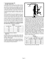
Страница 36: ...ap should be primed with suffi cient water to ensure proper condensate drain opera tion WARNING If you do not follow these instructions exactly a fire or explosion may result causing property damage p...

Страница 37: ...her source of ignition to check for gas leaks D Testing Gas Supply Pressure When testing supply gas pressure use the 1 8 N P T plugged tap or pressure post located on the gas valve to facilitate test...

Страница 38: ...ion for installations at eleva tions over 4500 feet 1372 m is the jurisdiction of local au thorities EL195DF units require no manifold pressure adjustments for operation at altitudes up to 10 000 feet...

Страница 39: ...or partial ground Compare the readings to the table below If the read ings exceed the maximum shown in table 1 make re pairs before operating the furnace 2 In addition measure the AC voltage from Lin...

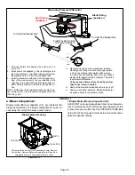
Страница 40: ...return air ple nums Insert manometer hose flush with inside edge of hole or insulation Seal around the hose with perma gum Connect the zero end of the manometer to the discharge supply side of the sy...

Страница 41: ...s 120VAC 10 3 Check amp draw on the blower motor with blower ac cess panel in place Motor Nameplate__________Actual__________ FIGURE 54 Check Motor AMP Draw Typical set up with upflow furnace shown kV...

Страница 42: ...up in center of burner ports 35 Reconnect exhaust piping and exhaust drain tubing 36 Reconnect flame roll out switch wires 37 Reconnect sensor wire and reconnect 2 pin plug from ignitor 38 Reinstall...

Страница 43: ...goes into 5 minute Watchguard Pressure Switch delay Once S18 closes a 15 second pre purge follows 4 The integrated control A92 energizes ignitor A 20 second warm up period begins 5 Gas valve opens fo...

Страница 44: ...E OFF COMBUSTION AIR INDUCER ON INDOOR BLOWER ON HEATING SPEED LED FLASHES CODE 11 PRESSURE SWITCH CLOSED GAS VALVE OFF COMBUSTION AIR INDUCER OFF INDOOR BLOWER OFF WITH DELAY Sequence holds until pre...

Страница 45: ...ETE YES 4 SECONDS YES HAS CONTROL RESET IGNITION SEQUENCE FOUR TIMES FLAME SIGNAL 1 5 MICROAMPS OR GREATER YES YES YES ROLLOUT SWITCH CLOSED LED FLASHES CODE 8 ROLLOUT SWITCH OPEN GAS VALVE POWER OFF...

Страница 46: ...UT SWITCH CLOSED LED SLOW FLASH RATE REMAINS UNCHANGED THROUGHOUT COOLING CYCLE THERMOSTAT CALLS FOR COOLING COMPRESSOR CONTACTOR AND SYSTEM FAN ENERGIZED WITH 2 SECOND DELAY COOLING SPEED COMPRESSOR...

Страница 47: ...ENS SYSTEM FAN SWITCHED TO COOL SPEED EAC TERM REMAINS ON THERMOSTAT OPENS MANUAL FAN SELECTION MADE AT THERMOSTAT CONTROL G ENERGIZES SYSTEM FAN AT FAN SPEED EAC TERM ENERGIZED NO YES YES NO SYSTEM F...

Отзывы: