14
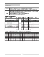
ALARM CODES
CODE
SIGNAL
DESCRIPTION
EFFECT
RESET
E ID
External alarms from following protection components:
- Compressor protector module open:
COMPACTAIR From 48D (F11-12) / 100D (F11-F12-F13-F14)
AIRCOOLAIR From 48D (F11-F12) / 100D (F31-F33) / From 128D (F31-F32-F33)
- Outdoor fan protection open:
COMPACTAIR (F13-F14) / (F15-F16) 100D
AIRCOOLAIR (F13-F14) / From 100D (F35-F36)
- High pressure switch protection open (HP1-HP2)
- Low pressure switch protection (LP1-LP2)
When digital input ID3 is opened the alarm message E ID is displayed
Only alarm indication
Reset automatically when input ID3 is closed
CHECK POINTS
1. Check power board operation:
- Verify the position of jumper J3 on power board
,
position 1-2 (
INT-ID COM
).
- Do a shortcut connection between GND and ID3 on pcb. With this action a by pass for the protection line is
done.
- If the alarm disappears and the control operates, the problem must be one of the protection components
(go to points 2 - 3 - 4 - 5).
è
If the alarm does not disappear, power board is defective.
2. Check compressor protector module:
- Verify that motor operating current is within values.
- Verify proper rotation direction of compressor.
- Measure discharge pipe temperature, protector trip up to 140ºC.
- Check for loss of charge or extremely high compression ratio.
- Check operation of compressor module protection:
- Check the module for possible loose connection, cable breakage.
- Measure compressor internal thermistor chain in a cold condition (after the compressor has sufficiently
cooled down). Disconnect the terminal S1 and S2 to measure thermistor resistance, which must be between
150 and 1250 ohms. If the thermistor chain has a higher resistance / 0 ohms (short circuit) /
¥
ohms
(open circuit) compressor is defective.
- Verify compressor module, remove terminals from M1 and M2, terminal S1 and S2 should be connected,
switch on power supply, control voltage 220V must be available between terminal T2 and T1, without
taking out power supply check continuity between M1 and M2.
è
If there is not continuity, the compressor internal protection is defective.
COMPRESSOR MOTOR PROTECTOR MODULE
Technical specifications:
Normal PTC resistance: 150 to 1250 Ohms
Trip resistance: > 4500 Ohms ± 10%
Reset resistance: < 2750 Ohms ± 10%
Module time delay: 30 minutes ± 10%
Compressor protector module is based on the temperature
resistance of thermistor chain (five PTC-resistances): one
thermistor for each phase (NAT 80ºC) on winding upper
side, the fourth thermistor on winding lower side (NAT 140ºC)
and the fifth thermistor in the discharge port (NAT 140ºC).
Operating description:
3. Check outdoor fan internal protection (internal thermal contact or thermal relay):
- Check continuity, loose connections and verify that motor operating current is within value.
4. Check high pressure switch protection (HP):
- Check continuity, loose connections and verify high pressure switch connection to refrigerant pipe.
- Check high pressure values, pay special attention to HP values during defrost cycle.
5. Check low pressure switch protection (LP):
- Check continuity, loose connections and verify low pressure switch connection to refrigerant pipe.
- Verify refrigerant charge, air flow and filters.
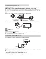
For D units (2 STAGE COOLING / 3 STAGE HEATING) alarm EID indicates the alarms of both circuits together,
the alarm code is displayed by either safety relay (R1 - R2) deactivation.
Each circuit includes a safety relay (R1 - R2), R1 for circuit one and R2 for circuit two. The relay for each circuit
will remain closed (activated) until any of the protection devices (compressor protection module, outdoor internal
protection, high pressure switch, low pressure switch) are activated.
The control only produce alarm indication, the compressor and outdoor fan for each circuit will be stopped by its
corresponding protection devices (compressor protector module, outdoor fan protection, high pressure switch
protection, low pressure switch protection)
and safety relay (R1 - R2). Therefore when the alarm EID is displayed
one of the circuits will be operating despite the order circuit is stopped due to activation of its corresponding safety
chain.
After an alarm occurs the safety relay will be activated again, when the cause that produce the failure is reset and
the indoor fan is switched OFF.
To switch off indoor fan:
Switch OFF-ON power supply,
Set the unit on [OFF] mode and then set [COOL/HEAT
] mode again through the terminal.
To solve the problem will be necessary to identify on which circuit had happen the failure and after that follow the
check points for each protection component.


