


32
• Air Wash
The air wash is a portion of the incoming combustion air that is split
off and routed to flow across the inside of the glass door which helps
the viewing area stay clean.
• Auger (A)
A motor powered screw device that transfers the fuel from the hopper
to the feed chute to deliver pellets to the Burn-Pot.
• Auger Motor (B)
Drives the auger. Motor specifications are: .4 Amp, 1.28 RPM (revolu-
tions per minute). The auger motor turns the auger, lifting pellets up
the auger tube. The pellets are then dropped down a tube and into
the Burn-Pot. The auger is controlled by the control board.
• Blower, Convection (Room Air) (C)
The blower function is to transfer the heat from the appliance to heat
the room air.
• Blower, Combustion (Exhaust) (D)
It has a radial impeller to deliver more air to the Burn-Pot. It pulls
air into the Burn-Pot by creating a negative pressure. This is done
by extracting the exhaust gases out of the firebox and pushing the
exhaust downstream to the flue exit.
• Convection Blower Snap Switch (F140-20F, N/O*) (E)
This switch is located on the snap switch bracket (along with the high
limit and pre-high limit snap switches) just inside the right side door
on the back of the firebox. When the stove reaches 140° F this switch
automatically closes and activates the convection blower. When the
stove drops below 120° F the switch opens again turning the convec-
tion blower back off.
• High Limit Snap Switch (Manual Reset) (L225F N/C*) (F)
This switch is located on the back right of the stove in the snap switch
bracket with the convection blower snap switch and pre high limit snap
switch. It is designed to shut down the stove if it senses an overfire
condition (it opens at 225° F). This snap switch has a reset button
on it and will not allow the stove to start-up until the reset button has
been pushed.
• Low Limit Proof of Fire Snap Switch (Ceramic, F140-10F, N/O*)
(G) - This switch is located on the combustion blower. This switch
will close at 140° F and will not open until it reaches a temperature
of 130° F. It is designed to shut down the stove if it does not detect
the heat of a fire at the end of the initial startup period or if your stove
has emptied the hopper.
• Pre High Limit Snap Switch (F200-40F, N/C*) (H)
This snap switch is N/C and opens at 200° F. It will close when the
temperature cools to 160° F. It is located on the back right of the stove
in the snap switch bracket with the high limit snap switch and blower
snap switch. This switch will slow the feed rate of your auger motor
if your convection blower is running at a less then optimal setting and
heating up the stove beyond normal heating levels.
• Hopper Lid Switch (I)
This switch is located on the upper right rear of the hopper. It detects
whether the hopper lid is open and will turn off the auger motor if the
hopper lid is not properly closed. When opening the hopper, when
refueling, do not allow the hopper lid to remain open too long or the
fire may extinguish. NEVER DISCONNECT OR BYPASS THIS SWITCH
FOR ANY REASON.
• Hopper (J)
The hopper is where the pellets are stored.
• Igniter (K)
The automatic igniter is designed to light the fuel when the stove is
in the lighting mode. The igniter superheats air that is pulled through
the Burn-Pot by the combustion blower to light the fuel. The igniter
remains energized for the first seven minutes of the lighting sequence.
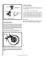
• Vacuum Switch (L)
The vacuum switch located on the right rear of the stove behind the
firebox on the vacuum switch bracket. If a low pressure is created in
the firebox by a leak, opening the front door, a blocked flue, or unsealed
ash pots, the vacuum switch will sense it and cause the stove to go
into a shutdown mode.
Some other possible causes for this switch to trip are as follows:
• High altitude or other misc. environmental conditions affecting
exhaust flow.
• Improper venting system.
• Burn-Pot (M)
This is where combustion occurs.
Electrical Generator Operation
Your Bella™ pellet stove can be powered with a gas driven electrical gen-
erator. However, the generator’s electrical regulator may not be compatible
with the stove’s electronics. The higher the quality of the generator, the
greater the chance that it is compatible with the stove.
* N/C = Normally Closed
N/O = Normally Open
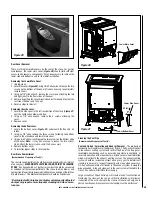
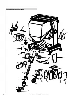
COMPONENT DEFINITIONS
Figure 44
A
B
C
D
E
H
F
G
I
K
L
M
J
Содержание BELLA
Страница 43: ...43 NOTES ...