
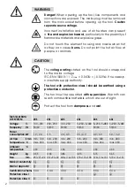

Technical Data
LHS SYSTEM
20S
20L
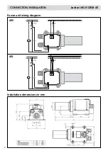
40S
40L
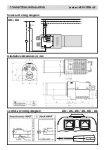
60S
60L
Voltage
V~
100 – 230
200 – 230
100 – 230
3
×
230 – 3
×
440 3
×
230 – 3
×
480 3
×
230 – 3
×
480
Frequency
Hz
50/60
50/60
50/60
50/60
50/60
50/60
Power
consumption kW
1.0 / 2.0
3.3
2.0 / 4.0
2.0 / 4.0
4.0 / 6.0
5.0 – 16.0
Air flow
l/min.
min. 100
min. 200
min. 200
min. 200
min. 300
min. 400
Temperature °C
max. 650
max. 650
max. 650
max. 650
max. 650
max. 650
Ambient
°C
temperature
<
65
<
65
<
65
<
65
<
65
<
65
Weight
kg
0.55
0.65
0.85
0.95
3.15
3.65
Size
mm
237
×
97
×
92 267
×
97
×
92 246
×
112
×
103 276
×
112
×
103 379
×
116
×
137 379
×
116
×
137
Mark of conformity
¬
¬
¬
¬
¬
¬
Marl of approval
†
†
†
†
†
†
Certification scheme
CCA
CCA
CCA
CCA
CCA
CCA
Protection class I
‡
‡
Protection class II
¶
¶
¶
¶
2
Danger!
When opening up the tool, live components and
connections are exposed. The mains plug must be removed
from the main socket before opening up the tool.
Caution
separate source voltage.
Incorrect installation and use of air heaters can present
a
fire and explosion hazard
, particularly in the proximity of
flammable materials and explosive gases.
Do not touch the element housing and nozzle when hot
as they can cause
burns.
Do not point the hot air flow at
people or animals.
WARNING
The tool must be operated
with supervision
. Warmth can
reach combustible materials, which are out of sight.
The
voltage rating
stated on the tool should correspond
to the mains voltage.
IEC/EN 61000-3-11; Z
max
=
0.047
Ω
+ j 0.029
Ω
. If necessary,
consultate supply authority.
Protect the tool from
dampness
and
wet
.
100
480
CAUTION
The tool with protection class I should be earthed using a
protective conductor.


