background image

13

Leica VT1000 S – Microtome

5.1

Setting up the instrument

1. Put the mains switch at the back of the instrument to the 

OFF 

position.

2. Make sure the mains cable is connected correctly to the instrument.
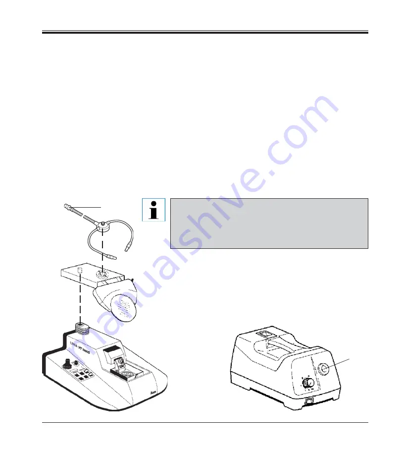
3. Attach the magnifier carrier.
4. Insert a blade into the knife holder.
5. Insert the buffer tray.
6. Insert the knife holder.
7. Connect magnifier carrier / optional fiber optics light guide to the cold

light source as shown below: insert plug 

(1) 

of the fiber optics light

guide into socket 

(2) 

at the cold light source.

8. Connect the optional foot switch at the rear of the instrument.
9. Plug the mains cable into the mains power wall outlet.
10. Switch the instrument 

ON

 (mains switch).

5.

Operation

1

2

The Leica VT1000 S is equipped with a wide-range power
pack to cover voltages from 100 V to 240 V.
Once the mains switch is turned on, the instrument carries
out an initialization process: after performing a slight for-
ward movement, the knife moves to the final rear position.

Содержание VT1000 S

Страница 1: ...Instruction Manual Leica VT1000S V1 6 English 11 2007 Always keep this manual near the instrument Read carefully prior to operating the instrument Leica VT1000S Vibrating blade microtome...

Страница 2: ......

Страница 3: ...ortheinstrumentserialnumberandyearofmanu facture please refer to the name plate at the back of the instrument Leica Biosystems Nussloch GmbH The information numerical data notes and value judgments co...

Страница 4: ...VT 1000 S controls and their function 14 5 3 Adjusting the amplitude 18 5 4 Working with the VT 1000 S on a daily base 19 5 5 Daily routine maintenance switching the VT1000S off 22 6 Trouble shooting...

Страница 5: ...on for all inquiries For any inquiries please specify Instrument type Serial number 1 2 Qualification of personnel The Leica VT1000S should be operated by trained laboratory personnel only Prior to st...

Страница 6: ...ioninthecountryofoperation appropriateinstructionsforcompliance with such requirements must be added to this manual Readthisinstructionmanualcarefullybeforeattemptingtoworkonoroperate the instrument 2...

Страница 7: ...touch the cutting edge of knives and blades Do not leave knives blades and bladed knife holders unprotected Take adequate protective measures to elimi nate risk of infection Protective clothes accordi...

Страница 8: ...L 70 x 40 mm Specimen orientation 330 Section thickness selection 1 999 m in 1 m steps Magnifier assy Standard accessory 2 x Ambiance conditions Working temperature range min 10 C to max 40 C Relative...

Страница 9: ...roperties 3 2 Overview VT1000S Buffer tray S Emergency stop switch not visible here Fixture for magnifier Fiberoptics optional Magnifierglass Cold light source Leica CLS 100 optional Knife holder Cont...

Страница 10: ...height adjustment LEDsindicatelimitpositions Pause button stopssectioningprocess Control knob for sectioning speed Indication of selected section thickness or totalized section thickness in m Selectio...

Страница 11: ...613 1 x VT1000S Basic instrument 0472 35612 3 Specimen discs S 50 mm non orientable 0463 27404 Buffer tray S 0462 30132 5 Countersunk screw M 5x8 2101 77121 2 Hose clamps 0481 41952 Knife holder S for...

Страница 12: ...lete Connect the drain tube Fig 13 1 of the cooling bath at the underside of the instrument 1 Ensure that the loose end of the drain tube is closed tightly with the matching stopper Secure the loose e...

Страница 13: ...ide to the cold light source as shown below insert plug 1 of the fiber optics light guide into socket 2 at the cold light source 8 Connect the optional foot switch at the rear of the instrument 9 Plug...

Страница 14: ...75 10 2 50 10 Speed rotating potentiometer with scale Function Continuous knife feed adjustment from 0 05 2 5 mm s Knife return stroke is performed at constant speed of 5 mm s The additional locking l...

Страница 15: ...ife edge past the speci men block and press once more to set the second sectioning window limit Press START to deactivate V Max The knife edge moves back to the first sectioning window limit and resum...

Страница 16: ...r position The REV FORW switch can also be used to stop a sectioning stroke which has been activated by pressing the START STOP button LED indication with adjusting button DISP and CLR function keys F...

Страница 17: ...nife is in motion the UP DOWN toggle switch is inoperational For the DOWN motion the toggle switch can be locked in the DOWN position for the UP motion the switch must be pressed and held in the UP po...

Страница 18: ...Adjusting the amplitude To obtain excellent sectioning results the amplitude requires adjust ment according to the specimen type being sectioned To this end With a 2 5 mm Allen key loosen the clamping...

Страница 19: ...necessary fill crushed ice into the cooling bath 3 Fill the buffer tray 1 with cooled buffer solution Fix the specimen onto the specimen disc with cyanoacrylate adhe sive 19 2 Insert the specimen disc...

Страница 20: ...angle every time you change the knife The clearance angle needs to be readjusted only when required by a different application e g different type of tissue to be sectioned To insert the blade loosen t...

Страница 21: ...ONING WINDOW button Switch the SINGLE CONT button to CONT Push the START STOP button The instrument will now trim the specimen at the selected trimming thickness until you push the START STOP button o...

Страница 22: ...able surface Remove the specimen using a single edge blade Then remove re mains of cyanoacrylate adhesive from the specimen disc Remove the buffer tray and drain it Make sure to dispose properly of th...

Страница 23: ...sion of knife and speci men holder Audible sound signal Return stroke is not complet ed Audible sound signal Return stroke is not complet ed Clearance angle adjustment If a clearance angle wider than...

Страница 24: ...ue to locking function of the UP DOWN button With the UP DOWN button locked in the DOWN position the instrument was switched off via the main switch at the rear of the instrument switched on again wit...

Страница 25: ...action Button s jammed or defective Locking function REV of REV FORW button defective Locking function REV of REV FORW button defective Feed mechanism defective Important electronic compo nent defect...

Страница 26: ...ched height adjustment of speci men via buffer tray User has tried to select a specimen thickness via the button which is below the minimum value 0 m or above the maximum 999 m Switch the instrument o...

Страница 27: ...Service Do not use the instru ment when in this condition The visible clamping screws have become loose during sectioning These symptoms may occur from time to time and are un avoidable as the clampin...

Страница 28: ...ush Remove the buffer tray empty it and rinse it separately with water see also page 22 7 1 Cleaning the instrument Always remove the knife blade before detaching the knife holder from the instrument...

Страница 29: ...connect the mains plug To exchange the fuses carefully open the sealing cover at the rear of the instrument with a small screw driver Insert the screw driver into the small gap on the extreme left 1 R...

Страница 30: ...rge specimens Vise S 046327409 Knife holder S 046230131 Buffer tray S 046230132 Buffer tray S double walled 046330365 Specimen disc S 50 mm non orientable 046327404 Specimen disc S orientable 04632740...

Страница 31: ...vise individually according to the size of the specimen In order to relocate the fixed clamping jaw unscrew the two screws 4 and move the clamping jaw to the desired position Retighten the screws The...

Страница 32: ...rent positions to adjust the vise individually according to the size of the specimen In order to relocate the fixed clamping jaw unscrew the two screws 4 move the clamping jaw to the desired position...

Страница 33: ...he magnifier after the magnifier has been mounted into the fixture Then connect the fiber optics to the cold light source Ref no 0502 30028 Magnifier To be inserted into the fixture Ref no 0462 31191...

Страница 34: ...s of your Leica sales organization or the organiza tion from which you have purchased the contractual product shall apply exclusively Service information If you are in need of technical customer servi...

Страница 35: ...control and laboratory use Part 1 General requirements EN 61326 1 1997 EN 61326 1 1998 Electrical equipmentl for measurement control and laboratory use EMC requirements Part 1 General requirements EN...

Страница 36: ...36 Instruction manual V1 6 11 2007 11 Peoples Republic of China...

Отзывы: