background image

Printed Documentation 

Remote access wizard: Configure Serial port 

Background Information 

The Configure Serial port settings, allow configuring a connection to a computer, for when the GR10 receiver is 

connected directly via a serial cable.  

The settings for the Com port on the computer must match the settings for the serial connection on the receiver. 


Setting Descriptions 

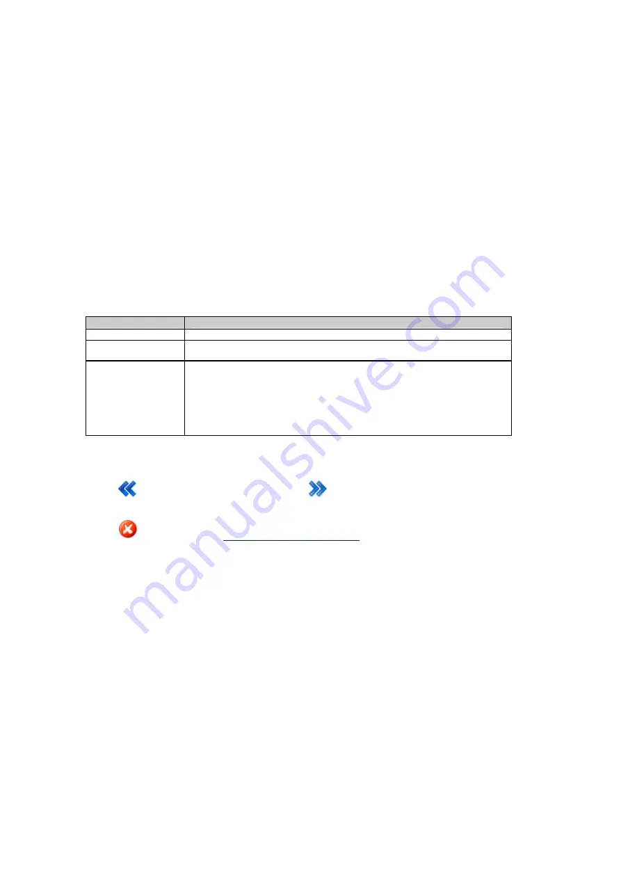
The table below describes the settings that can be configured on the Configure serial port page. 


Setting


Description


Port name


Serial port is always selected here. The field can not be edited.


Baud rate, Parity, 
Data bits, St p bits


o

Select the port settings for the communication between the receiver and the PC's 
Com port. 


Flow control


Defines which kind of handshake is used.  

• 

None: No handshake. 


• 

RTS/CTS: Handshake in both directions. 


Press 

 to go back to the previous wizard step.  Press

to continue to the next wizard step. 

Press 

to cancel and return to 

Spider and remote access: Overview

 . 


176 

Содержание GR10

Страница 1: ...Leica GR10 Operational Manual Online Help ...

Страница 2: ... Interface User Interface GR10 Overview 29 GR10 Web interface 36 5 Getting started Operation Overview 45 Network technology and protocol overvie Equipment Setup 47 Working with the Memory Device Use DynDNS and DHCP to automatically assign a host name and all network parameters to a GR10 62 Use DynDNS to assign a host name to a Access the web interface for the first time and change the default user...

Страница 3: ...1 External Devices 243 External Devices Overview Leica surveying controllers CS10 CS15 245 Working with Radio Modem and GSM D Configure a meteo device step by step 253 Configure a tilt device step by step External Oscillator 254 12 Default settings Default settings Overview 255 Format receiver settings via Web interfa Format receiver settings via instrument buttons step by step 258 Restore default...

Страница 4: ...tory Structure of the Menu Bar 293 Web interface Directory Structure of the Appendix E Directory Structure of the Memory Device 296 Directory Structure of the Memory Devic Appendix F GR10 default settings 297 Appendix F GR10 Default settings Appendix G Event log messages 307 Event log messages Appendix H Glossary 309 Glossary Overview Antenna Reference Point ARP 311 CDMA Dynamic Host Configuration...

Страница 5: ...te Access An overview of the GNSS Spider remote access process and the requirements that are required 9 How to A list of step by step guides to help you configure and use the receiver 10 Support resources A summary of the support resources available for a GR10 user 11 External devices This section explains which external devices can be used with the GR10 Includes step by step guides for each devic...

Страница 6: ...on Contents The Contents tab displays a table of contents Books and pages represent the categories of information in the online help system When you double click a closed book it opens to display its content sub books and pages When you double click an open book it closes When you click pages you select topics to view in the right hand pane of the HTML Help viewer Index The Index tab displays a li...

Страница 7: ... search How to use Search step by step To use the online help search follow these steps Steps Description 1 To find information with advanced full text search click the Search tab and type the word or phrase you want to find 2 Click GO and select a topic listed below Searches are not case sensitive so you can type your search in uppercase or lowercase characters You may search for any combination ...

Страница 8: ...m the Select Content drop down list select Only the selected fram e Select As selected on screen to only print a highlighted section of text 6 If you are happy with what is displayed on the screen press Print Mozilla Firefox Steps Description 1 Open the Online Help topic 2 Right click in the topic frame on the right 3 Go to This Frame Print Frame 4 The Print window opens 5 Select the Printer Name ...

Страница 9: ...ardware installation and common accessories Software setup is described in detail along with the technical specifications GNSS Reference Station and Networks An Introductory Guide Offers practical advice on how to set up and run individual GNSS reference stations and networks of stations and to provide the services that are required GNSS Networks and Reference Stations Equipment List Detailed list...

Страница 10: ... typical reference station setup and the most common accessories that can be used with a GR10 Unpacking the GR10 instrument A list of the minimum items delivered with a GR10 Instrument Components A labelled diagram of the GR10 GR10 Operation An overview of how to operate the GR10 Power Supply An overview of the power supply options for the GR10 A detailed description of every Web Interface page is...

Страница 11: ...rts a variety of external devices including communication meteo and tilt Satellite tracking The GR10 can track GPS L1 L2 including L2C L5 GLONASS L1 L2 Galileo E1 E5a E5b AltBOC SBAS Once the first operational Galileo satellites are available a software update will be required The GR10 instrument is designed to support Compass The Compass signal definition is not fully finalised although test sign...

Страница 12: ...CMR Modern user friendly Web interface GUI available in different languages Seamless integration with Leica GNSS Spider Robust lightweight metal housing Fully ruggedised to IP67 including a ruggedised Ethernet port Simple mounting for IT rack cabinet and wall mount Unit is also stackable Built in communications Slot in port Integrated device management for external devices Supports DHCP DNS DynDNS...

Страница 13: ...t c Antenna cable d GFU housing including Radio GSM device e Meteo sensor f Tilt sensor g Serial cable h SD card i Optional radome for AR25 j GNSS antenna AR10 k GNSS antenna AR25 l GNSS antenna AS10 m Antenna cable n Optional lighting protection o Ethernet hub p Computer running GNSS Spider or Web interface q Ethernet cable r GR10 s Slot in radio GSM device t Antenna cable u Power supply v Oscill...

Страница 14: ...e possible Main components Component Description GR10 To provide the storage and streaming of raw satellite data Antenna To receive the satellite signals from the GNSS Global Navigation Satellite System satellites Web interface Web based tool to configure the GR10 Leica GNSS Spider The reference station software including comprehensive receiver control and configuration file download and firmware ...

Страница 15: ... Additional equipment such as cables antennas and power supply required for a complete reference station installation are delivered with the GR10 when ordered The Component overview shows a typical reference station installation and the accessories that can be ordered For further information on accessories please refer to the GNSS Reference Station Equipment List 14 ...

Страница 16: ...ts a User interface b USB and SD card cover c Front rubber bumper d Back rubber bumper e GNSS Antenna port f External Oscillator port g Serial port P1 h Ruggedised Ethernet port i Power port j Communication Slot in port Antenna P3 k Communication Slot in port P3 15 ...

Страница 17: ...ure and operate the GR10 A detailed description of every Web Interface page is included in the Web Interface section Supported operating systems for the GR10 Web Interface Windows XP Professional SP2 and SP3 32 bit Windows Vista Enterprise SP2 32 bit Windows Server 2008 SP1 64 bit Windows 7 Ultimate 32 bit 64 bit Support internet browsers for the GR10 Web Interface Browser Supported version Intern...

Страница 18: ...e will be overwritten In this case use the Web interface exclusively for settings that are not available in GNSS Spider To operate Leica GNSS Spider refer to the GNSS Spider Remote Access for basic information Leica GNSS Spider Online Help for advanced information Requirement GR10 Leica GNSS Spider v4 0 or later must be installed GNSS Spider Features Simultaneous configuration and communication wi...

Страница 19: ... Documentation Protect and manage access to RTK correction services using the Spider Business Center advanced user access management Related topics Keyboard Web Interface Overview GNSS Spider Remote Access 18 ...

Страница 20: ...s CE is the underlying operating system on the GR10 Measurement Engine firmware ME4 xx fw This file contains the Measurement Engine firmware for the GR10 This firmware is always included in the GR firmware file however it is also possible to load this file separately should an update become available Software upload Softw re for a Description GR10 All software is stored in the System RAM of the in...

Страница 21: ...irmware can be found on the Status Receiver Information page on the GR10 Web interface Related topics Is my firmware up to date Firmware upgrade step by step Firmware upgrade using Leica GNSS Spider Loading a Language file Status Receiver Information Receiver setup Firmware management Receiver setup Language management 20 ...

Страница 22: ...ystems OR 110 V 240 V AC to 12 V DC power supply unit 722409 supplied by Leica Geosystems OR GEB171 439038 battery connected via a cable OR Car battery connected via a converter cable supplied by Leica Geosystems Y cable GEV243 774438 Y cable can be used with GEV238 power supply and GEB171 battery or the existing 12 V power supply 722409 The black Lemo connector on this cable only supports the use...

Страница 23: ......

Страница 24: ...er before installing the GR10 including Installation location Installation orientation Cable installation Installation options Detailed diagram of possible installations Rack mount Wall Cabinet Mount Free Standing Stacking Tripod A detailed description of every Web Interface page is included in the Web Interface section ...

Страница 25: ... connector points are pointing downwards Cable installation Ensure that the cables between the instrument and antenna are positioned to prevent them from becoming bent stretched or squeezed For the installation of the cables the general rules for the installation of electrical wiring apply Please consider that a well planned and thoroughly carried out electric installation not only protects the ca...

Страница 26: ...ist Rack Mount Together with the rack mount accessory kit the GR10 can be easily mounted into a standard 19 inch IT rack If space in the rack is limited then the rubber bumpers on the GR10 can be removed The total height of the rack kit and instrument is then 2U If the bumpers are removed please remove the small feet from the mounting brackets The radio GSM antenna must be installed on the outside...

Страница 27: ...he rubber bumpers on the GR10 can be removed If the bumpers are removed please remove the small feet from the mounting brackets The radio GSM antenna must be installed on the outside of the rack if a slot in radio or GSM device is used Attach the Radio GSM antenna cable to port P3 a Radio GSM antenna b Antenna bracket c Radio GSM antenna cable d Wall mount accessory bracket e Wall mount accessory ...

Страница 28: ...ng Stacking The GR10 is designed to allow stable free standing installation and stacking for easy configuration of multiple receivers When stacking multiple GR10 instruments on top of each other the rubber bumpers must be on 27 ...

Страница 29: ...low attachment to all Leica Geosystems Tripods When using the GR10 on a tripod the rubber bumpers must be on a AS10 b GNSS antenna carrier with 5 8 inch screw c Tribach d Tripod e Antenna cable f GR10 Related topics Before Installation Description of the system Overview 28 ...

Страница 30: ...tton Button combinations LED Indicators on GR10 A detailed overview of the LED indicators on the GR10 and their status USB and SD Card Cover A detailed overview of the USB and SD card slot Web Interface Web Interface Login Web interface User Interface A detailed overview of the layout of the web interface and a brief description of the major components 29 ...

Страница 31: ...en 10 40 The LED indicates the overall power status If a second external power source is connected using a Y cable both power sources are used simultaneously When the LED is yellow the power level on both external power sources is low 10 40 red The power level of the connected power source is between 1 10 Recommended user action Switch to a new power source SD card LED off No SD card inserted or p...

Страница 32: ...on status red Active logging sessions are configured but the SD card is full or no navigated position is available Recommended user action Check the SD card and the tracking status RT out data stream LED off No active real time out data stream or power is off green One or more real time data streams are configured and active Data is being streamed red Data streams are active but no data is streame...

Страница 33: ...een steady light at the power LED indicates that the instrument is turned on and ready ON OFF button Button Function ON OFF If GR10 already off Turns on GR10 when held for 2 s If GR10 already on Turns off GR10 when held for 2 s Hold the ON OFF button for 10 s to force the instrument to turn off Instrument settings and some data can be lost when using this method 32 ...

Страница 34: ...ing LED is flashing green Press the Function button until the LED flashes quickly to START all configured logging sessions if the Raw data logging LED is flashing green OR If any logging session had been active the Raw data logging LED is flashing red Press the Function button until the LED flashes quickly to STOP all active logging sessions if the Raw data logging LED is flashing red After loggin...

Страница 35: ...gine has been initialised the LED and instrument functionality goes back to general behaviour Format the receiver settings Activate dual button functionality as described above Press the Function button until the Power LED starts flashing slowly Press the Function button until the LED flashes quickly to set all configured instrument settings back to factory default values After the system format i...

Страница 36: ... possible While other SD cards can be used Leica recommends to only use Leica SD cards and is not responsible for data loss or any other error that can occur while using a non Leica card Unplugging connection cables or removing the SD card during data logging or streaming can cause loss of data It is recommended to switch off the instrument before removing the SD card The Leica USB Card Reader 767...

Страница 37: ...ly restricted web interface access the login as guest button can be used This login allows access to all Status information The login page is not shown if the web interface access level is set to unrestricted The web interface home page is opened directly For security reasons it is not recommended to set the web interface access to unrestricted To change the access setting go to Receiver Setup Acc...

Страница 38: ...ent system time Below the menu bar that is used to navigate in the web interface Below on the right is the Status block that summarizes the most important receiver functionality information This status block is visible on every page Left of the status block is the content area This contains the actual information for this page e g status information a configuration page or links to receive support...

Страница 39: ...e configured logging sessions and data streams the satellite tracking an overview of the ports in use and the power and memory available GNSS Management Configure all GNSS data related settings such as logging sessions data streams and the tracking settings Or enter site specific information such as the site name position and antenna details Receiver setup Configure all receiver related settings s...

Страница 40: ...up or the automatic file delete for each logging session The SD card is full Data logging is stopped Recommended user action Immediately activate the Smart clean up or the automatic file delete for each logging session Data stream status The data stream status is shown with an icon and the number of currently active data steams This number includes both outgoing and incoming streams One or more da...

Страница 41: ...he receiver was turned on This icon is only shown if the receiver is turned on because of an active wake up session Smart clean up status Smart clean up is active Smart clean up is inactive Indicates active logging sessions are available and Smart clean up is deleting data from all or some of these sessions Recommended user action Please check the remaining space on the SD card and delete old data...

Страница 42: ...ove the cut off angle Tracked L1 Tracked GPS satellites on L1 Tracked L2P Tracked GPS satellites on L2P Tracked L2C Tracked GPS satellites on L2C Tracked L5 Tracked GPS satellites on L5 GPS L5 tracking can only be activated when the GPS L5 option is installed on the receiver GLO GLONASS satellite system pop up information Sat available Number of GLONASS satellites available above the cut off angle...

Страница 43: ...ng satellites The number of currently tracked satellites is shown Indicates that the satellite system is activated but the receiver is not tracking Indicates that the satellite system is not activated Internal this receiver is configured to use the internal receive clock default setting TCXO OCXO Rubidium Cesium The receiver is configured to use the listed external oscillator If an external oscill...

Страница 44: ...utton For better clarity the hints are hidden per default Press the Hints button to display the information After pressing the button a blue box appears underneath each field to explain the setting Press the Hints button again to hide the hints Pop up boxes Pop up boxes provide quick access to additional status information that per default is hidden for better clarity A pop up box opens when the u...

Страница 45: ...clicking on the number of tracked satellites in the Tracking status block Press the button in the upper right corner to close the pop up box Tool tips In the web interface tool tips are used to explain the functionality of icons and buttons Move the mouse over an icon to show the tool tip Move the mouse away from the icon and the tool tip disappears Related topics LED Indicators on GR10 44 ...

Страница 46: ... Important safety directions for using the SD card and a step by step guide on how to insert and remove an SD card Step by step guides Use DynDNS and DHCP to automatically assign a host name and all network parameters to a GR10 Use DynDNS to assign a host name to a GR10 with static IP Access the web interface for the first time and change the default user Activate Leica support access step by step...

Страница 47: ...ces to be added to the network with little or no manual intervention As a result directly after connecting it the network device can be accessed straightaway by a preconfigured host name In case of a GR10 this host name is GRxxxxxxx where xxxxxxx has to be replaced by the serial number of the GR10 Dynamic vs static IP address Network devices may have a permanent so called static IP address or they...

Страница 48: ... card slot For more information on how to work with the SD card refer to Working wi h the Memory Device t 3 Turn on the GR10 4 Attach the antenna cable for example the GEV194 1 8 m antenna cable to the instrument s antenna port and to the connector on the antenna To access the instrument via Ethernet or USB refer to Setup via Web Interface over Ethernet and DHCP Install USB drivers Setup via Web I...

Страница 49: ...supporting DHCP plug an Ethernet cable with a RJ45 connector into the RJ45 Ethernet port on the back of the GR10 3 Connect the other end of the cable with a network device of your LAN e g hub switch or router 4 Turn on the GR10 5 Open a browser window on your computer 6 Type GR into the browsers address field where is the serial number of the instrument For example GR1700001 7 The GR10 Web interfa...

Страница 50: ...onnect the crossed Ethernet cable to the GR10 receiver and your PC 2 On the PC open the Network Connections properties 3 Select the Network connection used with the crossed Ethernet cable right click and select properties 4 In the General tab highlight Internet Protocol and press Properties 5 Select Use the following IP address and enter IP address 192 168 0 1 Subnet mask 255 255 255 0 49 ...

Страница 51: ...Printed Documentation 6 Press OK 7 Open a browser window and enter 192 168 0 3 to open the GR10 web interface 50 ...

Страница 52: ...ng a USB cable you must first install USB drivers To install the USB drivers refer to Install USB drivers for Windows XP operating systems Install USB drivers for Windows Vista operating systems Install USB drivers for Windows 7 operating systems Only one GR10 can be connected to the computer via USB at a time 51 ...

Страница 53: ... and check the box I have read the instructions These instructions are listed in detail in the following steps 12 Click Finish to exit the wizard 13 Click Yes to restart the system so all changes take effect For Windows XP users with Service Pack 3 Windows does not require a restart 14 Loosen the screw on the SD card USB port cover 15 Open the SD card USB port cover 16 Plug the USB cable into the ...

Страница 54: ...and type in the IP address 192 168 254 2 to access the GR10 web interface 30 Configure the GR10 for all required settings 31 Use the default User name Admin and Password 12345678 After logging in the first time you must create a new user account including a new user name and password The default user account can then be deleted Go to Access the web interface for the first time and change the defau...

Страница 55: ...to InstallShield Wizard for Remote NDIS based LGS device connection window appears 13 Click Next 14 The Ready to Install the Program window appears 15 Click Install The drivers will be installed on your computer 16 Click Install this driver software anyway every time a window pops up saying that the software has not passed the Windows Logo testing 17 The InstallShield Wizard Completed window appea...

Страница 56: ...5678 After logging in the first time you must create a new user account including a new user name and password The default user account can then be deleted Go to Access the web interface for the first time and change the default user for a step by step guide Please make sure that JavaScript is allowed to be executed Check the browser settings if you should have problems using the web interface Tro...

Страница 57: ...llShield Wizard for Leica Viva GR USB drivers window appears e 13 Click Next 14 The Ready to Install the Program window appears 15 Click Install The drivers will be installed on your computer 16 Click Continue Anyway every time a window pops up saying that the software has not passed the Windows Logo testing 17 The InstallShield Wizard Completed window appears 18 Read the instructions and check th...

Страница 58: ...5678 After logging in the first time you must create a new user account including a new user name and password The default user account can then be deleted Go to Access the web interface for the first time and change the default user for a step by step guide Please make sure that JavaScript is allowed to be executed Check the browser settings if you should have problems using the web interface Tro...

Страница 59: ...e IP address 192 168 254 2 to access the GR10 Web interface 8 Use the default User name Admin and Password 12345678 After logging in the first time you must create a new user account including a new user name and password The default user account can then be deleted Go to Access the web interface for the first time and change the default user for a step by step guide 9 Configure the GR10 for all r...

Страница 60: ...S GR Device 3 Select Internet Protocol TCP IP and click on Properties 4 Pick option Use the following IP address and choose an address in the range of 192 168 254 1 192 168 254 255 except 192 168 254 2 which is the IP of the GR10 Use subnet mask 255 255 255 0 5 Disconnect and reconnect the USB cable Windows Vista Step Description 1 Go to Start Control Panel Network and Internet View Network Status...

Страница 61: ... is writing data to the card To remove the SD card safely turn off the instrument beforehand Ensure that the instrument is off before inserting the SD card Switching on the instrument will ensure the necessary folder structure is available on the SD card Failure to follow these instructions could result in data loss and or permanent damage to the card Related topics Insert and remove an SD card in...

Страница 62: ...he SD card USB port cover 3 Place the SD card into the slot The card should be held with the contacts downwards and facing the slot Do not touch the contacts 4 Slide the card firmly into the slot until it clicks into position 5 To remove the SD card gently press inwards on the card to release it from the slot 6 Place the SD card USB port cover back over the slot and tighten the cover screw Related...

Страница 63: ... an IP address automatically 5 Click on Save changes to save all settings Use DynDNS to assign a host name to a GR10 with static IP This procedure requires a DynDNS server As a result the assigned host name can be used to access the receiver within the network If no DHCP server is available all network parameters have to be entered manually Please contact your network administrator to get valid pa...

Страница 64: ...e Save changes button to save all settings 9 If the password meets the password requirements the new user account will be saved and thus be shown in the list of configured users 10 To avoid unauthorized access it is recommended to delete the default user 11 For this log out from the web interface and log in now using the new user account 12 Go to Receiver Setup Access Management and use the Delete...

Страница 65: ...utton to save all settings Configure tracking settings step by step This section explains how to configure the tracking settings Step Description 1 Access the web interface 2 Go to page GNSS management Tracking 3 On the General tab the basic tracking options can be configured 4 Select the satellite systems you want to track using the check boxes 5 In the row Satellite signals specific signals of a...

Страница 66: ... wizard you can activate the logging session In this case the logging will immediately start If you do not activate the check box Activate session the session will be saved with all its settings but it will not be started Press the Save changes button to save all settings Configure a data stream step by step This section explains how to configure a new outgoing real time data stream using a radio ...

Страница 67: ......

Страница 68: ... data related settings such as logging sessions data streams and the tracking settings Or enter site specific information such as the site name position and antenna details Receiver setup Configure all receiver related settings such as network connections FTP push locations and the user management Or use the tools to upgrade the receiver firmware add new option keys or switch to your preferred lan...

Страница 69: ...Each satellite system tab shows the satellites tracked on each frequency and their current status information such as elevation azimuth SNR values and health Available tabs General GPS GLONASS GALILEO SBAS Data streams Displays a list of all configured outgoing data streams and all incoming data streams from attached devices meteo and tilt devices Logging sessi ns o View detailed information about...

Страница 70: ...on every GR10 receiver L2C tracking GR10 receivers can be activated to track GPS L2C GNSS Spider OWI The Leica GNSS Spider software can connect and control any GR10 receiver per default No additional option is needed Loaded firmware Description Maintenance end The expiry date of the software maintenance contract For information on Custom Care Packages visit the Leica Geosystems web page or contact...

Страница 71: ...Printed Documentation Related topics Status Overview Status Receiver information Options GNSS management Receiver setup 70 ...

Страница 72: ...article numbers go to GR10 Options Field description The table below describes the fields in the Status Receiver information Options tab Press the Refresh icon to update the displayed data Instrument details Description Installed options Lists all options installed on the receiver Options currently not installed Lists all options that are currently not installed on the receiver but are available f...

Страница 73: ... in geodetic coordinates X Y Z Shows the navigated position of the receiver in Cartesian coordinates Shows the entered reference position of the receiver in Cartesian coordinates Local time The current time in the local time system Position latency The latency of the computed position Latency is typically attributed to the time required for data transfer and computation of position HDOP The Horizo...

Страница 74: ...manac The date and time of the GPS almanac Date of GLONASS almanac The date and time of the GLONASS almanac Only available for receivers with the GLONASS option Date of GALILEO almanac The date and time of the GALILEO almanac Only available for receivers with the GALILEO option Time signal Shows the oscillator configured on the receiver If no external oscillator is used Internal clock is shown Sat...

Страница 75: ...s not currently being used in the position calculations S N L2C The signal to noise ratio on L2C The number is shown in brackets if the signal is not currently being used in the position calculations S N L5 The signal to noise ratio on L5 The number is shown in brackets if the signal is not currently being used in the position calculations URA The User Range Accuracy URA as transmitted in the broa...

Страница 76: ...Azimuth The azimuth of the satellite in degrees S N L1 The signal to noise ratio on L1 The number is shown in brackets if the signal is not currently being used in the position calculations S N L2 The signal to noise ratio on L2 The number is shown in brackets if the signal is not currently being used in the position calculations Health Description Healthy Lists the PRN numbers of the healthy sate...

Страница 77: ...tly being used in the position calculations S N E5a The signal to noise ratio on E5a The number is shown in brackets if the signal is not currently being used in the position calculations S N E5b The signal to noise ratio on E5b The number is shown in brackets if the signal is not currently being used in the position calculations S N ABOC The signal to noise ratio on Alt Boc The number is shown in...

Страница 78: ...llite options are available on the receiver Press the Refresh icon to update the displayed data Field Description Sat The Pseudo Random Noise PRN number of the satellite System The SBAS satellite system S N L1 The signal to noise ratio on L1 The number is shown in brackets if the signal is not currently being used in the position calculations Related topics Tracking General Tracking GLONASS Tracki...

Страница 79: ...ption Icon Data stream is active Data stream is inactive Type Message The configured message type and version Click on the underlined message type to open a list box showing how many satellites are used Data rate The configured rate at which data is sent out Last sent The latency of the last outgoing data stream sent in seconds The connection type and port over which the data stream is sent out Co...

Страница 80: ...immediately Rate The configured data rate for the NMEA message Connection port The connection type and port over which the data stream is sent out BINEX Description Icon Data stream is active Data stream is inactive Message The configured BINEX messages activated for the outgoing data stream Click the listed BINEX messages to view additional properties BINEX message properties The table below desc...

Страница 81: ...s overview GNSS management Outgoing data stream Streaming session wizard Configure realtime out data stream Streaming session wizard Configure LB2 data stream Streaming session wizard Configure NMEA data stream Streaming session wizard Configure BINEX data stream 80 ...

Страница 82: ...yed temperature pressure and humidity reading Temperat re u The temperature recorded by the device at the data time Pressure The pressure recorded by the device at the data time Relative humidity The relative humidity recorded by the device at the data time Tilt Description Name The name of the configured tilt device Serial number The serial number of the configured tilt device Data time The time ...

Страница 83: ... Smart clean up To activate or deactivate a session go to GNSS management Logging session Sessions tab To activate or deactivate Smart clean up go to GNSS management Logging session Smart clean up tab Name The name of the logging session Type The configured logging session type MDB RINEX or Hatanaka and if the session is continuous or timed Runtime The time that the session has run or is running s...

Страница 84: ...tes if logging SNR values in the RINEX file is activated yes or deactivate no in the logging session Archive data to Shows where the logging session data is archived Clicking on the SD Card link opens an FTP connection to the SD Card This is only possible when the FTP server access is enabled To enable FTP server access go to Receiver Setup FTP server The FTP access to the SD card may not work in ...

Страница 85: ...ocumentation For RINEX and Hatanaka logging sessions it will always list the observation file name 10o Related Topics Logging sessions Overview GNSS management Logging sessions GNSS management Smart clean up 84 ...

Страница 86: ...point for NTRIP connections configured for the data stream Connections The number of connected users on each port With the default setting a maximum of one user is possible If the Multi Client option is installed on the receiver and the configuration is set accordingly more than one connection per TCP IP port is possible In this case the number of connected users and the number of possible connect...

Страница 87: ...nnected to the port Click on the IP address to open a pop up window The pop up window shows the data volume sent and received on this port and lists the connected host IP address and the connection duration HTTP FTP ports Description Icon An icon is shown indicating the port status Disconnected Awaiting connection s Connected Port type Shows if HTTP or HTTPS is active and differentiates between FT...

Страница 88: ...rupted Action should be taken by an administrator to ensure correct receiver operation General message A general message indicates a problem with a receiver task that does not influence the most important functionality Investigate by checking the receiver configuration Information message Information messages reflect events from the normal receiver activity No action is required by the administrat...

Страница 89: ...a and time Show verbose messages Activate or deactivate verbose messages Verbose messages provide additional information about the receiver status that are not shown per default in order to keep the event log clearer Verbose mode will be deactivated after closing the browser logging out of the receiver or rebooting the receiver Content Filter the messages by the selecting the messages content cate...

Страница 90: ...ernet connection Subnet mask The subnet mask for the connection Gateway The gateway for the connection DNS servers The IP addresses of the DNS servers that are used Data sent The amount of data sent out from this connectio n Data received The amount of data received by this connection MAC address The MAC address of the receivers ethernet device Mobile internet Description Status The status of the ...

Страница 91: ...ived The amount of data received by this connection in bytes Device name States that this USB conection is established via the USB host port DynDNS Description Status Indicates if updating the IP address of the receiver at the DynDNS service was successful Service provider The DynDNS service provider configured Last IP up ate d The date and time when the IP address was last updated at the DynDNS s...

Страница 92: ... describes the fields in the Status System resources page Power Description Available capacity The available capacity on the external power source SD Card Description Total size The total storage space available on the SD card Memory left The available storage space remaining on the SD card CPU load Description Current CPU usage Displays the current CPU load CPU loa history d Description Diagram T...

Страница 93: ...ure and edit logging sessions for writing MDB RINEX or Hatananka files Enable or disable the Smart clean up of logging session data on the receiver to ensure optimal use of the SD card size and data availability FTP locations Configure edit and delete FTP locations that are used to push data created by a logging session on the receiver to an external FTP server Antenna management Select the used r...

Страница 94: ... on the Site name and coordinates page Naming Description Site name Enter the name of the site This is a unique identifier for the location of the receiver The site name field can be left blank The maximum number of characters is 16 Only certain ASCII characters are allowed 0123456789 ABCDEFGHIJKLMNOPQRSTUVWXYZ abcdefghijklmnopqrstuvwxyz _ hyphen underscore period and space are also allowed Site c...

Страница 95: ... ASCII characters are allowed 0123456789 ABCDEFGHIJKLMNOPQRSTUVWXYZ abcdefghijklmnopqrstuvwxyz _ hyphen underscore period and space are also allowed Marker number Enter a marker number The marker number is used to occupy the equivalent entry in the RINEX header when creating RINEX files for this site If no Marker Number is entered then it will default to the Site Code The maximum number of charact...

Страница 96: ... the reliability of the coordinate of the reference station the reference station should not be used for relative positioning A position adjustment is necessary to calculate the exact coordinate for the reference position The current position helps to set up reference station receivers to collect data for this position adjustment The Save button must be pressed to store the current position Restor...

Страница 97: ...satellite systems depends on the installed receiver options When activating a satellites system check box all frequencies listed below are activated When deactivating a satellites system all frequencies below are deactivated if possible GPS L1 and L2 are always active The Tools Options page provides an overview of all purchased options that are currently activated on the receiver and a detailed de...

Страница 98: ...l oscillator is selected but not connected the receiver will not track any satellite signals Restore default values Press to restore the default values The restore default button fills all fields with the default values and stores these values Pressing the save button is not necessary When accepting the confirmation message all settings on this page are overwritten with the default settings SBAS n...

Страница 99: ...Printed Documentation Related topics GNSS management Tracking GPS GNSS management Tracking GLONASS GNSS management Tracking GALILEO 98 ...

Страница 100: ...lites to the same value Satellite The PRN satellite number Health from almanac Shows the health setting for this satellite as received from the broadcast navigation message NA is shown for satellites where no health information is available in the ephemeris User defined health Shows the configured health setting for each satellite Either Auto Healthy or Bad This field can be edited via the list bo...

Страница 101: ...ll satellites to the same value Satellite The PRN satellite number Health from almanac Shows the health setting for this satellite as received from the broadcast navigation message NA is shown for satellites where no health information is available in the ephemeris User defined health Shows the configured health setting for each satellite Either Auto Healthy or Bad This field can be edited via the...

Страница 102: ... all satellites to the same value Satellite The PRN satellite number Health from almanac Shows the health setting for this satellite as received from the broadcast navigation message NA is shown for satellites where no health information is available in the ephemeris User defined health Shows the configured health setting for each satellite Either Auto Healthy or Bad This field can be edited via t...

Страница 103: ...t Data streams overview Tab Description GNSS management Outgoing data stream Configure outgoing realtime LB2 Leica Binary NMEA or BINEX messages from the receiver GNSS management Incoming data streams Configure incoming meteo and tilt data streams to the receiver 102 ...

Страница 104: ...low describes the fields in the Outgoing data streams tab Setting Description Icon Data stream is active Data stream is inactive To activate or deactivate a data stream press the Activate icon Stream Type The configured outgoing data type Type Message The configured outgoing message types Connection The configured connection type Device The configured device used for transmitting the outgoing data...

Страница 105: ...ming data streams Outgoing data stream wizard Select data stream Outgoing data stream wizard Configure realtime out data stream Outgoing data stream wizard Configure LB2 data stream Outgoing data stream wizard Configure NMEA data stream Outgoing data stream wizard Configure BINEX data stream Outgoing data stream wizard Connection Outgoing data stream wizard Configure TCP IP server Outgoing data st...

Страница 106: ...The table below describes the settings that can be configured on the Select data stream page Setting Description Data stream type Select the data stream type Realtime LB2 NMEA BINEX Press to continue to the next wizard step Press to cancel and return to GNSS management Outgoing data stream 105 ...

Страница 107: ...oadcast data for third party receivers CMR Compacted formats used to broadcast data for third party receivers RTCM 2 x Type 1 2 Differential and Delta Differential Code GPS corrections Use for DGPS applications An accuracy of 0 5 5m rms can be expected at the Rover Additional messages sent 3 RTCM 2 x Type 2 9 GPS Partial Correction Set and Delta Differential GPS Corrections Use for DGPS applicatio...

Страница 108: ...s real time services with significantly reduced bandwidth Additional messages sent 1006 1008 1033 RTCM 3 Extended ephemeris RTCM standard for correction transmission including message types 1004 1012 satellite ephemeris GPS data 1019 and GLONASS ephemeris data 1020 Further information go to RTCM Messages Types Realtime message formats Reference station ID Enter a reference station ID The reference...

Страница 109: ...fore the time slots are at 0 00 s and at 0 50 s With three reference stations the time delay is 0 33 s The time slots are at 0 00 0 33 and 0 66 s The following settings are dependant on the selected version and message type Data rate Select the rate at which data will be sent Coordin te rate a Select the rate at which coordinates will be sent Info rate Select the rate at which the Reference Statio...

Страница 110: ...e to stream LB2 data raw code and phase data for all tracked satellites 2 Select the message type to be sent out Message D LB2 D Message supports GPS L1 and L2 and GLONASS L1 and L2 data Message E LB2 Message additionally supports GPS L5 and Galileo signals and is more compact 3 Select the rate to send the measurement data Satellite data Activate to stream satellite data and send out ephemeris dat...

Страница 111: ...essage check boxes that are to be output A detailed description of each NMEA message is contained in Appendix B NMEA Messages Output Select to output the NMEA message either a och or immediately t ep Rate Select the data rate for the NMEA messages Output delay Define an output delay for the NMEA message Press to go back to the previous wizard step Press to continue to the next wizard step Press to...

Страница 112: ...of the following messages BINEX 0x00 Site Metedata output control BINEX 0x01 GNSS Navigation Information output control BINEX 0x7d Receiver Internal State output control BINEX 0x7e Ancillary Site Data Prototyping output control BINEX 0x7f GNSS Observable Prototyping output control Rate list box Select the data rate for the BINEX messages When new data available The receiver will send the message w...

Страница 113: ...all to allow clients to connect to the receiver Furthermore since the data stream is now sent to a PC port the number of connections to the data stream is not limited by the receiver NTRIP server source This mode allows the receiver to act as Ntrip Server and to provide data to an Ntrip Caster In terms of TCP IP the Ntrip server mode is in fact a TCP client mode As an Ntrip Server the receiver con...

Страница 114: ...rom Specify the number of users that are allowed to connect to the data stream via TCP IP Minimum of 1 user maximum of 10 users This setting is only available for receivers with the GRL115 Multi Client option key loaded For all other receivers the number of users is fixed to 1 The option can be purchased from Leica Geosystems Limit access range Select the range of IP addresses which are authorized...

Страница 115: ...w sent to a PC port the number of connections to the data stream is not limited by the receiver Setting Descriptions The table below describes the settings that can be configured on the Configure TCP IP client page Setting Description Server IP address Enter the numeric IP address of the Server to connect to The IP range is from 1 0 0 0 to 223 255 255 254 TCP IP port Enter the TCP IP port of the r...

Страница 116: ...e page Setting Description Server IP address The IP address of the Ntrip server to connect to Enter the numeric IP address The IP range is from 1 0 0 0 to 223 255 255 254 including TCP IP port Enter the TCP IP port to connect to on the NTRIP server Mount point Enter the mount point The mountpoint is the identifier of a data stream on an Ntrip Caster It is needed to provide data to an Ntrip Caster ...

Страница 117: ...up The serial port settings for these devices are configured in Receiver settings Device Management Setting Descriptions The table below describes the settings that can be configured on the Configure serial port page Setting Description Baud rate Parity Data bits St p bits o Select the port settings for the communication between the receiver and the serial port Flow control Defines which kind of h...

Страница 118: ...y the radios listed in the Receiver settings Device Management page are supported The port settings for these radios are predefined and cannot be modified Setting Descriptions The table below describes the settings that can be configured on the Configure radio page Setting Description Device Select the radio device Channel Enter the channel that will be used on the device Press to go back to the p...

Страница 119: ...Setting Descriptions The table below describes the settings that can be configured on the Configure GSM Modem CDMA dial up page Setting Description Device Select the device name Only devices defined in the Receiver settings Device Management page are available for selection Pin code Enter the pin code for the devices SIM card Puk code The puk code is a security code for the SIM card for some devic...

Страница 120: ...elow describes the settings that can be configured on the Set streaming status page Setting Description Activate data stream Deactivate the data stream if you do not want it to run immediately Press to go back to the previous wizard step Press to cancel and return to GNSS management Outgoing data stream 119 ...

Страница 121: ...n Icon Data stream is active Data stream is inactive To activate or deactivate a data stream press the Activate icon Stream Type The configured outgoing session type meteo or tilt Device The configured meteo or tilt device connected to the serial port Port The configured port on the receiver receiving the meteo and tilt data Data rate The configured data rate Delete Press delete to permanently del...

Страница 122: ...ing data stream page the Incoming data stream wizard opens The wizard is a tool that guides you through the following stages of incoming data stream configuration Data stream types Meteo and tilt Device selection and configuration Data stream activation Related topics Data streams Overview GNSS management Incoming data streams Incoming data stream wizard Select data steam Incoming data stream wiza...

Страница 123: ...ribes the settings that can be configured on the Select data stream page Setting Description Data stream type Select the incoming data stream type Meteo Tilt Press to continue to the next wizard step Press to cancel and return to GNSS management Outgoing data stream or GNSS management Incoming data streams 122 ...

Страница 124: ...teo device page Setting Description Device Select from the list box all available meteo sensors available on the receiver Data rate Select the rate at which data is requested from the meteo sensor The following default settings are used for communication between the Meteo device and receiver Met3 Met3A Met4A default communication settings Communication setting Default setting Port name Serial Port...

Страница 125: ... port and parameters for incoming tilt device measurements Setting Description Device Select the device The Leica NIVEL210 is the only tilt device supported by the GR receiver Data rate Select the rate at which data is requested from the tilt device The following default settings are used for communication between the Tilt device and receiver NIVEL210 default communication settings Communication s...

Страница 126: ...t streaming status page Setting Description Activate data stream Deactivate the data stream if you do not want it to run immediately Press to store the data stream configuration Press to go back to the previous wizard step Press to cancel and return to GNSS management Incoming data stream Related topics Data streams Overview GNSS management Incoming data streams 125 ...

Страница 127: ...ions GNSS management Logging sessions overview Tab Description GNSS management Logging sessions Configure create or edit a logging session GNSS management Smart clean up Enable and disable the smart clean up of logging session files on the receiver 126 ...

Страница 128: ...session data files are not removed e g by autodelete or FTP push Activate the Smart clean up functionality to ensure that the SD card will not run full Field Descriptions The table below describes the fields in the Sessions tab Field Description Icon Session is active Session is inactive To activate or deactivate a session press the Activate icon Name The configured logging session name Click the ...

Страница 129: ...eld Description Session name The configured logging session name Data type The configured data type Session type The configured session type either continuous or timed Timed allows specific logging intervals to be defined Logging rate The configured rate at which the observations are logged Length of file The configured file length The file length defines how long data is written to one file befor...

Страница 130: ...ta types priority and session type Session timing Logging rates file lengths included observations Data handling configuration Logging session activation Related topics GNSS management Smart clean up Logging session wizard Create a new logging session Logging session wizard Session timing Logging session wizard MDB Logging session wizard RINEX Logging session wizard Compact RINEX Logging session w...

Страница 131: ...tab Setting Description Enable Smart clean up Active When the SD card is almost completely filled by logging session data the Smart clean up will first delete the oldest files with the lowest priority to create space for new files Note The logging session priority is configured via the first logging session wizard page Create a new logging session Once all data from low priority session is deleted...

Страница 132: ...sessions will then stop logging data Leave this setting unchecked if you don t want to loose old data and are unaffected by the possibility of all logging sessions stopping due to a full SD card Press to save any setting changes Click here to view the Smart clean up flow chart Related topics GNSS management Logging sessions 131 ...

Страница 133: ...ed in the folder structure when storing log files Data type Select the data type that shall be written MDB RINEX Compact RINEX Hatanaka Session priority Select the priority level to be used for Smart clean up of the SD card either high medium or low If Smart clean up is activated then the session priority will determine which logging session are stopped saved if the SD card is nearing capacity Rea...

Страница 134: ...file length only If a continuous session type is activated it will start logging immediately To stop logging manually deactivate the session via the GNSS management Logging sessions menu option Press to continue to the next wizard step Press to cancel and return to GNSS management Logging session Related topics Logging sessions Overview GNSS management Logging sessions GNSS management Smart clean ...

Страница 135: ...ogging and closes this file at 16 10h because the second interval ends Setting Descriptions The table below describes the settings that can be configured on the Session timing page Please note that the time settings will refer to the receivers defined Time zone To set the receivers Time zone go to GNSS management Site name and coordinates Setting Description Start logging at Configure the start ti...

Страница 136: ...h Create a wake up session Activate to create a wake up session with the same timing settings as this logging session When the check box is activated and the logging session is stored a wake up session with the same name is created This wake up session has the same time and repeat settings as the logging session After the logging session is stored and the wake up session is created both can be edi...

Страница 137: ...ion on the receiver Length of file Choose a value from 5 minutes to 24 hours The file length defines how long data is written to one file before a new file is created Dynamics Raw data for the MDB logging session can logged in static or moving kinematic mode Log doppler observations Activate or deactivate logging doppler observations to the MDB file Press to go back to the previous wizard step Pre...

Страница 138: ...e of the operator that is to appear in the RINEX file header Maximum number of characters allowed is 20 Only certain ASCII characters are allowed 0123456789 ABCDEFGHIJKLMNOPQRSTUVWXYZ abcdefghijklmnopqrstuvwxyz _ and a space are allowed If left empty the field in the RINEX header will be left blank Agency Enter the name of the agency that is to appear in the RINEX file header Maximum number of cha...

Страница 139: ...Printed Documentation Press to go back to the previous wizard step Press to continue to the next wizard step Press to cancel and return to GNSS management Logging session 138 ...

Страница 140: ...Enter the name of the operator that is to appear in the RINEX file header Maximum number of characters allowed is 20 Only certain ASCII characters are allowed 0123456789 ABCDEFGHIJKLMNOPQRSTUVWXYZ abcdefghijklmnopqrstuvwxyz _ and a space are allowed If left empty the field in the RINEX header will be left blank Agency Enter the name of the agency that is to appear in the RINEX file header Maximum ...

Страница 141: ...Printed Documentation Press to go back to the previous wizard step Press to continue to the next wizard step Press to cancel and return to GNSS management Logging session 140 ...

Страница 142: ...ins all FTP locations configured in Receiver setup FTP locations If an FTP location has not been configured prior to creating the logging session finish creating the current logging session and then create the FTP push location Via the logging session Edit functionality assign the FTP push location An FTP location contains all information such as server name user name and password needed to access...

Страница 143: ...settings that can be configured on the Set logging status page Setting Description Activate session Deactivate the logging session if you do not want it to run immediately Press to go back to the previous wizard step Press to save the logging session Press to cancel and return to GNSS management Logging session 142 ...

Страница 144: ...or GR receivers with the FTP push option installed Setting Descriptions The table below describes the fields in the FTP locations overview page Settings Description Icon The icon is shown when the FTP push location is used in a logging session FTP push locations showing this icon cannot be deleted Name The configured name of the FTP location Click the FTP location name to view additional propertie...

Страница 145: ... settings of an already existing location Create new FTP location Press to create a new FTP location FTP location properties The table below describes the content of the FTP location pop up box that is displayed when clicking on the underlined FTP location name Properties Description Name The configured name of the FTP location FTP server host The configured FTP server host name IP or URL FTP serv...

Страница 146: ...er a valid username to access the FTP sever account Password Enter the password of the FTP sever account Send commands Add a custom FTP protocol command which is executed directly after login This field can be left blank Use passive mode Activate or deactivate using the passive mode Using the passive mode is recommended as it improves communication robustness Test FTP location Press to test read a...

Страница 147: ...gement GNSS management Antenna Management overview Tab Description Select antenna Select an antenna and enter the height reading and measurement type Antenna management Upload new antenna files create new antennas and restore antenna default values 146 ...

Страница 148: ...ons The table below describes the fields in the Select antenna tab Calculate the antenna height reading contains detailed information for the Height reading and Measurement type Field Description Antenna From the list box select the antenna to be used with the receiver The list contains all default and user defined antennas Go to Antenna management to upload a new antenna file or manually define a...

Страница 149: ...e receiver The File upload page will open Installed antennas All antennas currently configured on the receiver are listed Type Shows the antenna type Default antennas are available in the factory default settings User defined antennas have been added manually Delete Press Delete to permanently delete the antenna The ADVULLANTENNA can not be deleted Edit antenna Press to edit the antenna settings T...

Страница 150: ... all fields with the default values and stores these values Pressing the save button is not necessary When accepting the confirmation message all settings on this page are overwritten with the default settings Related topics File upload Create Edit and Antenna GNSS management Select antenna 149 ...

Страница 151: ...eight Hook this value may be 0 See also GNSS Management Calculate the antenna height reading Vertical offset Vertical distance from the ARP to the point where the height reading is measured to If you are using slope height readings to a point above the physical reference plane this value must be negative See also GNSS Management Calculate the antenna height reading L1 phase offset L2 phase offset ...

Страница 152: ... ways the height of the antenna can be measured On the left the height is determined by measuring the slope distance to an offset point on the antenna On the right the height is measured by using a height hook Pillar setup Tripod setup HO Horizontal Offset VO Vertical Offset VR Vertical Height Reading VE1 Vertical Phase Center Offset for L1 VE2 Vertical Phase Center Offset for L2 BPA Physical Refe...

Страница 153: ...ed Documentation Slope measurement type Note If the Offset Point on the antenna is above the Physical Reference Plane BPA the Vertical Offset VO is negative Vertical measurement type Antenna Height VR VO 152 ...

Страница 154: ...eiver will not power down Wake up sessions can be configured in two ways using Receiver setup Wake up sessions or via the Logging session wizard See GNSS management Logging session for further information The time settings will refer to the receivers defined Time zone To set the receivers Time zone go to GNSS management Site name and coordinates When the receiver is powered down remote communicati...

Страница 155: ...below describes the fields in the Wake up sessions page Settings Description Icon Wake up session is active and running Wake up session is inactive or the last wake up session has ended Wake up session is active but is currently not running Name The configured name of the wake up session If a wake up session was configured when creating a logging session the name shown will be the logging session ...

Страница 156: ...calculated power down time and date of the last interval of this wake up session Select at to enter a specific power down time Select after to enter the interval length Select No end to configure an infinite wake up session No of intervals The total number of repeats for the session Time between intervals The time between power down of one interval and the power up of the next interval Interval le...

Страница 157: ...nce a session has been created Wake up at The date and time for the receiver to boot for the first time with this Wake up session Power down The date and time for the receiver to power down after the first wake up interval After Define the length of the wake up interval At Define the end time and date for the first wake up interval No end The receiver will not power down automatically after the wa...

Страница 158: ...te Wake up session Activate this check box to activate the wake up session Save the settings by pressing This will redirect to the Wake up session overview page where all configured wake up sessions are listed Related topics GNSS management Wake up sessions GNSS management Site name and coordinates 157 ...

Страница 159: ... for OWI based software such as GNSS Spider to the receiver Web server Set the HTTP port number or configure secure access to the web interface via an SSL Secure Socket Layer connection DynDNS Allow access to the receivers web interface when using a dynamic IP address by configuring and enabling the DynDNS functionality FTP server Configure access to the receivers FTP server SD card Device managem...

Страница 160: ...allows defining the access to the receiver via an internet connection Tab option Description Ethernet Configure the Ethernet settings which will the enable the receiver to be accessed via the internet Mobile internet Configure access to the receiver via the internet with a mobile phone device e g GSM 159 ...

Страница 161: ...t knowing the IP address assigned to the receiver by the DHCP server The default hostname for each receiver is GRxxxxxxx where xxxxxxx is the serial number DHCP is enabled per default When first connecting the receiver to a LAN that runs a DHCP server entering the default hostname in a browser window opens the receivers web interface The user does not need to know the IP address assigned to the re...

Страница 162: ...parate IP networks For example a Local Area Network may need a gateway to connect it to the Internet The format of the gateway is aaa bbb ccc ddd where aaa is a value ranging from 001 to 223 and bbb ccc and ddd are values ranging from 000 to 255 DNS settings Description Preferred DNS server The DNS Domain Name System server IP address which was obtained via DHCP if the option Obtain DNS address au...

Страница 163: ...IM card for some devices The Puk code needs to be entered when the pin code has been entered incorrectly more than three times The Puk code will unblock the SIM card APN Enter the access point name APN of a server from the network provider which allows access to data services Contact your provider to obtain the correct APN User name Necessary to access certain APN s Contact your provider for the A...

Страница 164: ... option Description User management View configured users Create new users Delete users Edit users details and password Access settings Configure the access restriction level for the web interface Access a link to the FTP server access restrictions page Create a new user Set password Configure the web interface user level Configure the FTP server access level 163 ...

Страница 165: ... user This will delete all corresponding user information from the SD card It cannot be undone Edit user Press to edit the selected users details and password Create new user copy Press to create a new user based on the existing user settings Create new user Press to create a new user Restore default values Restore the default user settings This will delete all users and load the admin user with t...

Страница 166: ...ng the save button is not necessary When accepting the confirmation message all settings on this page are overwritten with the default settings Related topics Access Management Access settings Access Management New user Edit User 165 ...

Страница 167: ...icial authorization is possible Partially restricted The user can see the Status information when opening the web interface in a browser window Display of the Configuration settings requires a user name and password to log in The settings available after login depend on the user status of the logged in user Fully restricted Requires a user name and password to show any information on the web inter...

Страница 168: ...quired GNSS management no login required no login required no login required no login required Receiver setup no login required no login required no login required no login required Unrestricted Support no login required no login required no login required no login required Status with login or guest login with login or guest login with login or guest login with login or guest login GNSS managemen...

Страница 169: ...ser level Select the web interface user level None This user has no access rights to the web interface in restricted mode In partially restricted mode the user can see the sensor status This functionality can be used for defining users with only FTP access Status Viewer The Status viewer can login and view the receiver status when the web interface access level is set to fully restricted GNSS mana...

Страница 170: ...Web interface access description The Web interface access description provides a summary of which menus will be available for each user depending on whether the selected Access to Web interface is Unrestricted Partially restricted or Fully restricted and the selected Web interface user level Administrator GNSS manager Status Viewer or None The Web interface user level is configured via Receiver se...

Страница 171: ...ess Change password only no access Partially restricted Support with login no access no access no access Status with login with login with login no access GNSS management with login with login no access no access Status with login Limited access Change password only no access Fully restricted Support with login no access no access no access Related topics Access Management User management Access M...

Страница 172: ...t is recommended to configure two remote access ports as a minimum to utilise the GNSS Spider feature backup communication Detailed information on this topic can be found in the GNSS Spider online help Mozilla Firefox does not support the use of certain ports Use a different internet browser if these ports need to be used Ports blocked by default in Mozilla Firefox browser Setting Descriptions The...

Страница 173: ...remote access wizard The wizard is a tool that guides you through the following stages of a remote access configuration 1 Connection type Select if you want to connect the GR10 to the Spider site server via TCP IP server TCP IP client Serial port Radio or GSM Modem CDMA dial up 2 Device selection and configuration 3 Activation of remote access Related topics Remote access wizard Connection Remote ...

Страница 174: ...client and connect to a configured IP address and port This way no port has to be opened in the firewall on the receiver side to allow clients to connect to it Serial port This setting allows connecting the receiver directly to a PC s communication port via a GR10 data cable with a RS232 connector Radio Use two 2 way radios to allow Leica GNSS Spider or other OWI based software to configure the re...

Страница 175: ...t can be configured on the Configure TCP IP server page Setting Description TCP IP port Enter the TCP IP port of the receiver for Leica GNSS Spider or other OWI based software to connect to Limit access range Select the range of IP addresses which are authorized to access the receiver The available IP range is from 1 0 0 0 to 254 254 254 254 Press to go back to the previous wizard step Press to co...

Страница 176: ...nnect to the receiver Setting Descriptions The table below describes the settings that can be configured on the Configure TCP IP client page Setting Description Server IP address Enter the IP address or URL of the Server to connect to The IP range is from 1 0 0 0 to 223 255 255 254 TCP IP port Enter the TCP IP port on the Server for the receiver to connect to Press to go back to the previous wizar...

Страница 177: ...able below describes the settings that can be configured on the Configure serial port page Setting Description Port name Serial port is always selected here The field can not be edited Baud rate Parity Data bits St p bits o Select the port settings for the communication between the receiver and the PC s Com port Flow control Defines which kind of handshake is used None No handshake RTS CTS Handsha...

Страница 178: ... settings of a device if needed Setting Descriptions The table below describes the settings that can be configured on the Configure Radio page Setting Description Device Select the radio device Channel The radio channel can only be changed if the radio is attached If the configured radio device is not attached the device will be stored with the default channel 1 or the last stored channel when the...

Страница 179: ...gs that can be configured on the Configure GSM Modem CDMA page Setting Description Device Select the device to be used The list shows all GSM Modem CDMA devices configured in the device management PIN code Enter the PIN personal identification number code for the device s SIM card PUK code The PUK PIN unblock key code is a security code for the SIM card used on some devices The PUK code needs to b...

Страница 180: ...page Setting Description Activate remote access Deactivate the port configuration if you do not want to open the port immediately Press to go back to the previous wizard step Press to store the new remote access configuration and return to Configuration Spider and remote access Overview Press to cancel and return to Configuration Spider and remote access Overview 179 ...

Страница 181: ...ty who signed the SSL certificate is the guarantee that a user is actually on your receivers web interface and not some other site To see more information on the SSL certificate of a secure website click on the icon in one of the browsers corners This will open a pop up box showing information about the web site and the trusted third party that issued the certificate For the standard SSL certifica...

Страница 182: ...er and the certificate is self signed by Leica Geosystems AG How do I install my SSL certificate and key When you have created an SSL key and an SSL certificate you will have two files that can be opened with a text editor such as note pad 1 Open the SSL certificate CRT file and copy the text into the SSL certificate window on the Receiver setup Web server page on your receivers web interface 2 Op...

Страница 183: ...port number if you wish to override the default settings The default ports are used automatically if the field is left blank Default HTTP port 80 Default HTTPS port 443 If the default ports are not used then the port number needs to be entered in the browser window when trying to access the web interface SSL certificate Paste a signed certificate in X 509 PEM format here Open SSL License Copyright...

Страница 184: ...the OpenSSL Toolkit http www openssl org 4 The names OpenSSL Toolkit and OpenSSL Project must not be used to endorse or promote products derived from this software without prior written permission For written permission please contact openssl core openssl org 5 Products derived from this software may not be called OpenSSL nor may OpenSSL appear in their names without prior written permission of th...

Страница 185: ...THEORY OF LIABILITY WHETHER IN CONTRACT STRICT LIABILITY OR TORT INCLUDING NEGLIGENCE OR OTHERWISE ARISING IN ANY WAY OUT OF THE USE OF THIS SOFTWARE EVEN IF ADVISED OF THE POSSIBILITY OF SUCH DAMAGE The keyboard short cuts CTRL C and CTRL V can be used to copy and paste the SLL certificate an web interface SSL key Paste an RSA private key in PEM format here Original SSLeay License Copyright C 199...

Страница 186: ...n online or textual provided with the package Redistribution and use in source and binary forms with or without modification are permitted provided that the following conditions are met 1 Redistributions of source code must retain the copyright notice this list of conditions and the following disclaimer 2 Redistributions in binary form must reproduce the above copyright notice this list of conditi...

Страница 187: ...F SUBSTITUTE GOODS OR SERVICES LOSS OF USE DATA OR PROFITS OR BUSINESS INTERRUPTION HOWEVER CAUSED AND ON ANY THEORY OF LIABILITY WHETHER IN CONTRACT STRICT LIABILITY OR TORT INCLUDING NEGLIGENCE OR OTHERWISE ARISING IN ANY WAY OUT OF THE USE OF THIS SOFTWARE EVEN IF ADVISED OF THE POSSIBILITY OF SUCH DAMAGE The licence and distribution terms for any publically available version or derivative of t...

Страница 188: ...requirements necessary for DynDNS Requirement Description DNS Server To use the DynDNS service it is necessary to have a DNS server installed in same network as the receiver A DNS server can find the IP address assigned to a hostname This is necessary because although the DNS server knows the hostname of the DynDNS service the IP address of the service can change The DNS server makes it possible t...

Страница 189: ...sing Email and FTP push make sure that the relevant SMPT and FTP ports are open For DynDNS service also either port 80 8245 or 443 have to be available The profile also needs to contain the IP of at least one DNS server that is run by your provider 3 Apply correct port numbers After you received a list of the available ports go to Receiver setup Web server and change the HTTP port accordingly Also...

Страница 190: ... registered at the selected DynDNS service Click here for further information on Hostname rules Username Enter the user name for login at the DynDNS service The characters allowed in a username are a subset of the ASCII character set and include the characters a through z A through Z digits 0 through 9 and the hyphen This rule is known as the LDH rule letters digits hyphen The use name is interpre...

Страница 191: ...eceiver If disabled FTP access to the receivers SD card is not possible Allow anonymous access Activate to allow read only access to anonymous users FTP control port Enter the TCP IP port where the FTP server listens for incoming connections Default 21 FTP data port range Enter the TCP IP port range used for data transfers Default 50000 51000 Session timeout Select the time in seconds after which ...

Страница 192: ...ver Tab option Description Modem Phone View all default and user defined modem and phone devices Create new modem and phone devices Delete modem and phone devices Edit modem and phone device details Check which modem or phone devices are currently in use Radio View all default and user defined radio devices Delete radio devices Check which radio devices are currently in use 191 ...

Страница 193: ...ication settings Type The device type default or user defined Group The device grouping GSM GPRS CDMA TDMA UMTS or modem Port The port the device can be connected to Delete Press delete to permanently delete the device Edit device Press to edit the device settings The edit device wizard will open Create new device copy Press to create a new device based on the settings of an existing device Restor...

Страница 194: ...ttings Description Icon Device is in use If a device is in use it cannot be deleted Name The device name Click the device name to view the device communication settings Port The port the device can be connected to Delete Press delete to permanently delete the device Restore all default phones and radios Press to restore the default values All deleted default devices are restored Related topics Dev...

Страница 195: ...e page Settings Description Device type Lists the device type Device name Enter or edit the device name Mobile internet capable Configure if the device can be used to access the internet Baud rate Parity Data bits Stop bit Flow control Set the device communication settings Press to continue to the next wizard step Press to cancel and return to Device Management Modem Phone 194 ...

Страница 196: ... only shown when Mobile internet capable is set to Yes on the New Edit modem phone page Settings Description Init string 1 Enter a valid AT command to initialize the device Init string 2 Enter a valid AT command to initialize the device Connect string Enter a valid AT command to connect to the internet Press to continue to the next wizard step Press to cancel and return to Device Management Modem ...

Страница 197: ... to initialize the device Init string 2 Enter a valid AT command to initialize the device Dial string Enter a valid AT command to connect to the device Hangup string Enter a valid AT command to end the network connection Escape string Enter a valid AT command to switch into command mode before using the hangup string Press to change settings Press to save the logging session Press to cancel and re...

Страница 198: ...server nam SMTP e Enter the IP address or the domain name of the SMTP server to be used Mail server port Enter the TCP port number of the SMTP server commonly used defaults 25 or 587 Mail server username Enter the username as configured for the SMTP server account Mail server password Enter the password as configured for the SMTP server account Send event email every Select the interval to send ev...

Страница 199: ...ettings to include verbose messages and use the download button in order to have all messages including the verbose messages This procedure should be applied before contacting support Verbose mode will be deactivated after closing the browser logging out of the receiver or rebooting the receiver Related topics Status Event log 198 ...

Страница 200: ...e Select the power failure recovery setting Always After a power failure the system will immediately start up even if there is very low power available This should only be selected when the system is powered by an external main AC DC power source This option is not recommended for systems powered by batteries as it could affect a deep discharge and even destruction of the battery Sudden loss only ...

Страница 201: ... almanac and reset and store the receiver settings Firmware management Load and delete firmware files Option management Load or delete options on the receiver This page lists all purchased options that are currently installed on the receiver Language management Upload language files from the computer to the receiver and select which language should be used Receiver settings backup Backup and uploa...

Страница 202: ...lt values This includes all communication settings Remote access to the receiver might no be possible after the reset When the receiver settings are reset all logging sessions and data streams are deleted View the GR10 default settings Keep communication settings Press to reset all receiver settings except the communication settings Always use this setting when formatting the receiver settings for...

Страница 203: ...oot Format SD card Format receiver settings and Initialize measurement engine if executed will result in the receiver rebooting Related topics Appendix F GR10 default settings Format receiver settings via Web interface step by step Format receiver settings via instrument buttons step by step 202 ...

Страница 204: ...SS Spider Loading a Language file Please ensure that there are no power interruptions during the firmware upgrade Setting Descriptions The table below describes the fields in the Firmware tab Firmware Description Loadable firmware files The name of the firmware file All firmware files loaded onto the SD card are shown Version The firmware version number Location The location of the firmware file D...

Страница 205: ...e is a later firmware version available on the Leica web site than the one installed on the receiver Version The firmware version number Required maintenance date Installing new firmware is only possible if a valid maintenance key is available Download from Leica website The link starts a download of the latest firmware from the Leica website Related topics Receiver setup File upload 204 ...

Страница 206: ...ntained in the Options tab Field Description Install option keys To install a new option either Key Enter the option key The key is contained in the option file You can copy and paste the key into the Key field or Upload new option file Press to upload a new option from the computer to the receiver Opens the File upload page Delete Press to delete the option file Install Press to install the optio...

Страница 207: ...INEX CMR CMR streaming 774430 GRL109 2 20Hz logging and streaming Enables streaming data with up to 20Hz 774431 GRL110 50Hz logging and streaming Enables streaming data with up to 50Hz Requires 774429 GRL109 774432 GRL111 FTP Push Enables FTP Push 774436 GRL115 Multi client Enables up to 10 client connections per data stream TCP IP server setup 778851 GRL116 Wake up Enables the wake up functionali...

Страница 208: ... Setting Descriptions The table below describes the fields in the Languages tab Setting Description Language Lists all language files loaded onto the receivers SD card Code A 2 letter abbreviation for the language file Release date The release date of the language file The English language file is always released with the firmware file No release date is listed for English Version The version numb...

Страница 209: ...gs file This backup file is then listed in the Available receiver settings list Please check the event log after installing a receiver settings file The event log will show if the installation was successful Setting Descriptions The table below describes the fields in the Receiver settings backup tab Setting Description Available receiver settings Lists all receiver setting files loaded onto or st...

Страница 210: ...File upload 1 Press Browse to select the new option language antenna receiver configuration or firmware file from the computer 2 Press the upload icon to complete the upload of the new file from the computer to the receiver 209 ...

Страница 211: ...eiver problems Menu option Description Properties Activate the automatic sending of dump file to NRS support everytime the receiver stops operating Support tool Enter a support case and send to NRS support with a file containing the receiver configuration and settings Leica Active Assist Allow access to your receivers web interface by Leica support staff Links A list of helpful links 210 ...

Страница 212: ...as a problem while operating it will automatically retrieve the necessary information and send it via FTP push to NRS support Please note that no email is sent to NRS support The pushed files are checked by the NRS team on a regular basis Operator Company Country Email Enter the details in each field and press The information will be transferred to the Support Support tool page If the automatic mo...

Страница 213: ...incident Description Enter a detailed description and work flow of the support incident The more information that is supplied at this stage the quicker we can assist you Existing incident ID Enter the incident ID if a support case already exists for the current receiver problem Press the Mail icon to send your support question to Network Reference Stations support In the case that the Leica SMTP s...

Страница 214: ...used if a support incident has been created and the receiver s serial number has been forwarded to Leica NRS support Disconnect button If the connection to the Active Assist server was accepted you will automatically be logged out from the web interface Leica NRS support staff will inform you when the Active Assist session has been finished Please do not log in during an Active Assist session as t...

Страница 215: ......

Страница 216: ...s the underlying operating system on the GR10 Measurement Engine firmware ME4 xx fw This file contains the Measurement Engine firmware for the GR10 This firmware is always included in the GR firmware file however it is also possible to load this file separately should an update become available Software upload Softw re for a Description GR10 All software is stored in the System RAM of the instrume...

Страница 217: ...rmware can be found on the Status Receiver Information page on the GR10 Web interface Related topics Is my firmware up to date Firmware upgrade step by step Firmware upgrade using Leica GNSS Spider Loading a Language file Status Receiver Information Receiver setup Firmware management Receiver setup Language management 216 ...

Страница 218: ... appears in the following places in the Event log on the Status Receiver Information page on the Receiver Setup Tools Firmware page The Firmware management page allows the user to upload the latest available firmware file directly to the GR10 s SD card Related topics GR10 Software Overview Firmware upgrade Status Event log Status Receiver Information Receiver setup Firmware management 217 ...

Страница 219: ...ation page If the Maintenance End date shown is later than in the corresponding release notes then this firmware can be loaded If the Maintenance End date is no longer valid then please contact your local Leica Representative to learn about Customer Care Packages CCPs that include software maintenance so that you can benefit from the latest software improvements 2 Obtaining the new firmware The fi...

Страница 220: ...ce the file upload is complete Using a FTP client Step Description 1 Open an FTP client such as Windows Explorer or any other software capable of establishing an FTP connection 2 Enter the IP address hostname of the GR10 and the username and password of a user with FTP server read write access 3 Copy the firmware file into the Transfer Firmware folder on the SD Card SD Card reader Step Description...

Страница 221: ...in the table 3 Click the Install button to install the new firmware This may take several minutes 4 The receiver will automatically reboot following the installation of the new firmware and you will be directed to the Log in page 5 To verify if the installation was successful go to the Status Receiver Information page and view the installed firmware versions Related topics GR10 Software Overview I...

Страница 222: ...Server and select the Site tab 2 Right click on the GR10 site and choose Firmware upgrade 3 Select the firmware file to be uploaded and press Upgrade 4 Leica GNSS Spider will automatically upload and install the new firmware and then reboot the sensor A message will appear in the GNSS Spider Watch View to confirm that the upgrade was completed successfully For further information refer to the Leic...

Страница 223: ...ceiver Setup Tools Languages page in the GR10 Web interface 2 Click Upload new language file 3 Click the Browse button and select the new language file 4 Click the Upload button to copy the file to the SD Card 5 You will be directed back to the Language management page once the file upload is complete 6 Click the Install button next to the desired language in the table Related topics GR10 Software...

Страница 224: ...f the GNSS Spider remote access process and the requirements that are required GNSS Spider GR10 configuration An overview of how settings are stored on the receiver when using GNSS Spider GNSS Spider logging session An overview of GNSS Spider logging sessions GNSS Spider data streams An overview of GNSS Spider data streams 223 ...

Страница 225: ...e lists all ports on the GR10 receiver that are open for any OWI based tool to connect to the receiver and change the settings via OWI commands The page also allows creating new OWI ports and editing or deleting configured ports Access to the GR10 receiver can be configured via TCP IP server connection TCP IP client connection NTRIP connection Serial port Modem Radio It is also possible to connect...

Страница 226: ...any configuration on the receiver If the GRL117 Extended OWI license is not available on the GR10 receiver a remote port can be configured and activated but can only be used by Leica GNSS Spider To check the currently installed licenses on the receiver go to Status Receiver Information The Receiver tab lists the GNSS Spider OWI option as default functionality The Licenses tab shows if the extended...

Страница 227: ...ctivates the logging session and deletes or creates the data streams All other logging sessions and data streams are not affected by a start or stop of a GR10 GNSS Spider site When the user selects Upload settings in the Leica GNSS Spider software all settings configured for this site are uploaded to the connected receiver Since this includes tracking settings changes of the site code and the rece...

Страница 228: ...arting the site in GNSS Spider Per default the logged MDB data is stored in the folder Data __spider on the receivers SD card This folder can be changed in the web interface configuration GNSS Spider will still be able to download the files Please note that a GNSS Spider logging session is always created with the priority setting high This means that if other logging sessions created via the web i...

Страница 229: ...configured in GNSS Spider is only visible and active on the receiver when the according site in GNSS Spider is started When the site is stopped the data streams are deleted from the receiver No data streams can be deactivated from GNSS Spider on the GR10 Data streams created in GNSS Spider and uploaded to the receiver can however be deactivated in the web interface of the GR10 228 ...

Страница 230: ...figure your receiver How to set up a mobile internet connection How to use DynDNS service on receiver How to backup and restore receiver settings How to configure an NTRIP data stream How to configure FTP push of logged data How to reset the receivers settings How to configure a Wake up session 229 ...

Страница 231: ...ce Check that the event log states that the GPRS device has been connected 3 Go to Receiver setup Network connections Open the mobile internet tab 4 Select the GPRS device from the drop down list If the used device is not available in the list open Device management to create a new user defined device For more information on creating a new device see Device Management New Edit modem phone device 5...

Страница 232: ...9 How to Related topics Slot in devices Device Management New Edit modem phone device Status Network connections 231 ...

Страница 233: ...e you want your sensor to be accessed with Enable wildcard use Mail exchanger functionality is not necessary Step by step Step Description 1 Attach and configure a mobile internet device Please see Network connections Mobile internet on how to configure the mobile internet device 2 Open the receiver s web interface and go to Receiver setup DynDNS 3 Enter the hostname that you entered when register...

Страница 234: ...gement is overwritten with the access settings stored in the backup file when installing a new set of receiver settings Make sure that the access settings stored in the backup file are known in order to prevent being locked out of the web interface Step by step backup receiver settings Step Description 1 Open the receiver s web interface in a browser window by typing in the receivers IP or host na...

Страница 235: ...n be from the same receiver or from a different receiver 5 Press Upload to load the file onto the receivers SD card Wait until the upload is finished The file is then listed in the Receiver settings backup page 6 Press the Install icon to install the new receiver settings on the GR10 or to restore a previous receiver configuration The receiver will reboot after installing the settings 7 After the ...

Страница 236: ... the mount point access details on an Ntrip caster must be available Step by step Step Description 1 Open the receiver s web interface in a browser window by typing in the receivers IP or host name 2 Go to the GNSS management Data streams 3 Press the Create new data stream to open the data streams wizard 4 Select the Data stream type you wish to stream via the Ntrip protocol Then press the Continu...

Страница 237: ...ng a file on the server and closing the FTP server connection 10 Press save changes to store the configured FTP push location This will redirect to the FTP push locations overview page where all configured FTP servers are listed Step by step use an FTP push location in a logging session Step Description 1 Go to GNSS management Logging sessions to create a new logging session or edit an existing lo...

Страница 238: ... name 2 Go to the Receiver setup Tools page 3 Select Reset all in the list box if all settings are to be deleted or select Keep communication settings default if all communication related settings must not be deleted 4 Press the Format receiver settings icon to set the receiver settings back to factory default If Reset all is selected remote access to the receiver is not possible anymore unless th...

Страница 239: ...t Satellites with bad health may transmit incorrect almanacs and ephemeris Step Description 1 Open the receiver s web interface in a browser window by typing in the receivers IP or host name 2 Go to the Receiver setup Tools page 3 Press the Initialize measurement engine icon to delete the almanac and ephemeris The receiver will stop tracking satellites and lose the navigated position It takes seve...

Страница 240: ...e Online help The online help is accessible via the web interface On each web interface page the help icon is available Clicking this button will open the online help related to the current Web interface page The help is open in a new browser window This provides quick assistance for the complete Web interface The online help can also be opened via the help link in the web interface menu The onlin...

Страница 241: ...ontacted by NRS support regarding the sent information Please note that the receiver must be connected to the internet for using the support tool For further information about the support tool please see Support Support tool Active Assist During a support incident a GR user may be asked by the Leica NRS support team to connect to the Active Assist server Via this tool the support team can access t...

Страница 242: ...h the latest documentation myService View the service history of your products in Leica Geosystems Service Centers and detailed information on the services performed on your products For your products that are currently in Leica Geosystems Service Centers view the current service status and the expected end date of service mySupport Create new support requests for your products that will be answer...

Страница 243: ......

Страница 244: ...ing a GFU device Insert and remove a SIM card step by step for an external GFU device LED indicators Slot in devices Devices fitting into the GR10 Slot in P3 Insert and remove a slot in device step by step Insert and remove a SIM card step by step LED indicators Routers switches and hubs Within a local network the GR10 has to be connected to some kind of network device This may be a router a switc...

Страница 245: ...s written into a special auxiliary file Configure a tile device step by step Oscillators An external oscillator can be used to provide a better quality time signal to the receiver than the receiver s own internal clock The same external oscillator can also be used with a number of receivers so that each receiver is guaranteed to be tracking satellites using the same time signal An external oscilla...

Страница 246: ...e of the GR10 using a CS10 or CS15 Step Description 1 Power on the GR10 2 Power on the CS10 or CS15 3 Connect the mini USB connector of the USB cable article number xxx with the R10 G 4 Connect the standard USB connector of the USB cable with the CS10 or CS15 5 On the CS10 or CS15 go to Start and open the Internet Explorer 6 Type in 192 168 254 2 in the URL line of the Internet Explorer 245 ...

Страница 247: ...m and GSM Devices Overview A variety of devices can be used with the GR10 including GSM Radio GFU devices connected via a serial port Slot in devices External modems connected via a serial port External radios connected via a serial port Related topics Serial Devices Slot in devices 246 ...

Страница 248: ...MC C US GFU19 GFU26 CDMA MultiTech MTMMC C CAN GFU25 Radios fitting into a GFU housing Radio GFU housing Satelline 3AS transceive GFU14 Connecting a GFU device Step Description 1 Connect the GEV167 GFU cable to the serial port on the GFU housing 2 Connect the GEV167 GFU cable to the serial port on the GR10 3 The GFU device is successfully connected to the instrument when the LEDs on the GFU are on...

Страница 249: ...Turn the coin anticlockwise to loosen the SIM card screw 5 Remove the SIM card screw from the housing 6 Using the pen press the small button of the SIM card slot to eject the SIM card holder 7 Take the SIM card holder out off the housing 8 Put the SIM card into the SIM card holder the chip facing up 9 Insert the SIM card holder into the SIM card slot the chip facing the connectors inside the slot ...

Страница 250: ...U19 US GFU25 CAN GFU26 US with CDMA MultiTech MTMMC C off download mode or device is off red call is in progress red long flash long break no SIM card inserted no PIN entered or network search user authentication or network login in progress red short flash long break logged onto network no call in progress red flashing red long break GPRS PDP context activated red long flash short break Packet sw...

Страница 251: ...escription 1 Loosen the screws of the Communication Slot in port P3 with the Allen key that is supplied with the slot in device 2 Remove the compartment cover and attach to the slot in device 3 Insert the slot in device into the P3 Slot in port The LED s on the device must face downwards 4 Tighten the screws All screws have to be tightened to ensure that the instrument is waterproof 5 Attach the a...

Страница 252: ...SLG1 2 Take the SIM card and a pen 1 Using the pen press the small button of the SIM card slot to eject the SIM card holder 2 Take the SIM card holder out of the SLG1 2 3 Place the SIM card into the SIM card holder the chip facing up 4 Insert the SIM card holder into the SIM card slot the chip facing the connectors inside the slot 251 ...

Страница 253: ...ng transferred red call is in progress red long flash long break no SIM card inserted no PIN entered or network search user authentication or network login in progress red short flash long break logged onto network no call in progress red flashing red long break GPRS PDP context activated red long flash short break Packet switched data transfer is in progress SLG1 2 with Telit 3G off device is off...

Страница 254: ...e sure that the settings of serial port P1 are identical to the settings of the serial port of the meteo device Configure a tilt device step by step Step Description 1 Use the serial cable article number XXX which is connected to the tilt device and plug it into the serial port the GR10 2 In the web interface go to page GNSS management Data s s Incoming data steams tream 3 Click on button Create n...

Страница 255: ...e technical specifications of the external oscillator port and the required cable Configure an external oscillator with a GR10 Step Description 1 Connect the oscillator cable with the external oscillator 2 Find the external oscillator port OSC on the back of the GR10 3 Connect the other end of the oscillator cable with the external oscillator port OSC 4 In the web interface go to GNSS management T...

Страница 256: ...rmat receiver settings via Web interface step by step Detailed information on the reformatting of the receiver settings using the Web interface Format receiver settings via instrument buttons step by step Detailed information on the reformatting of the receiver settings using the instrument buttons Restore default values A description of which buttons to use to restore default values Related topic...

Страница 257: ...at receiver settings step by step Follow these steps format the receiver settings Step Description 1 Select Receiver setup Tools Tools tab 2 In Format receiver settings select Keep communication settings or Reset all If Keep communication settings is selected the following communication settings will not be reset Spider and remote access ports Network connection settings Ethernet mobile internet D...

Страница 258: ...12 Default settings Related topics Receiver setup Tools Appendix F GR10 default settings Format receiver settings via instrument buttons step by step 257 ...

Страница 259: ...eceiver is turned on 1 Activate the dual button functionality Press and hold both the Function button and Power button for 2s until all LEDs are flashing red 2 After 1s the Raw data logging LED starts flashing green 3 Press the Function button 4 times until the Power LED starts flashing green 4 Press the Function button for 3 s to set all configured instrument settings back to factory default valu...

Страница 260: ...can be restored only for certain pages Access the page an press the Restore default values button This will fill all fields in this page with the factory default settings Then press to store the default settings and overwrite the user defined configuration in this page ...

Страница 261: ......

Страница 262: ...continuous tracking on E1 E5a E5b and Alt BOC Galileo four channels tracking SBAS Depending on the satellite systems and signals configured in GNSS management Tracking a maximum number of 120 channels is allocated Supported codes and Phases GPS Type L1 L2 L5 GR10 Carrier phase C Acode Carrier phase C code L2C and P2 code Carrier phase code GLONASS Type L1 L2 GR10 Carrier phase C Acode Carrier phas...

Страница 263: ... Carrier phase smoothed code measurements P2 code and or L2C code L2 AS on Carrier phase smoothed code measurements Patented Pcode aided code and or L2C code Carrier phase and code measurements on L1 L2 and L5 GPS are fully independent with AS on or off Code and Phase Measurement Precision irrespective whether AS off on Carrier phase L1 L2 0 2mm rms 0 2 mm rms Code pseudorange on L1 L2 2cm rms 2cm...

Страница 264: ...ca Geomatic Office LGO and on real time measurements The use of multiple GNSS systems can increase accuracy by up to 30 relative to GPS only Differential code The baseline precision of a differential code solution for static and kinematic surveys is 25 cm Differential phase in post processing Normal baseline with GR10 plus AS10 Static kinematic Horizontal Vertical Horizontal Vertical 5 mm 0 5 ppm ...

Страница 265: ...n the additional tracking settings configured on the instrument 4 GB card GPS L1 L2 L5 12 satellites Rate MDB only RINEX only Hatanaka only 2180 hours 450 hours 1700 hours 1s 3700 hours zipped 1700 hours zipped 4500 hours zipped 56550 hours 12650 hours 49700 hours 30s 95780 hours zipped 47380 hours zipped 108000 hours zipped 4 GB card GPS GLONASS L1 L2 12 10 satellites Rate MDB only RINEX on y l H...

Страница 266: ...ging at 1 Hz with only the power supply and antenna connected 3 1 W Logging and streaming at 1 Hz with power supply antenna and ethernet connected 3 5 W Power consumption 3 5 W typically 24V 150mA External supply voltage Nominal 12 V DC GEV71 car battery cable to a 12 V car battery voltage range 10 5 V 28 V DC Operating times Designed for continuous operation Battery external Type NiMH Voltage 12 ...

Страница 267: ...o be effectively counteracted by periodically drying out the instrument Connector types Type Protection PWR LEMO 1 female 5 pin Serial P1 LEMO 1 female 8 pin GNSS antenna TNC female P Slot in antenna TNC female Oscillator MMCX female Ethernet RJ45 ruggedised Serial ports Type Description Default setting P1 Baud rates 2400 115200 baud incl RTS CTS 115200 N 8 1 N Data output Raw data Almanac Ephemer...

Страница 268: ...ty 0 5 ppm maximum Wave shape Sinusoidal Connector MMCX female Internal Oscillator aligned to GPS time within 10 nanoseconds Please remove the External oscillator port cover before connecting the cable Ethernet network interface IEEE Standards 8002 3 10BASE T Ethernet 802 3u 100BASE TX Fast Ethernet 802 3 Auto negotiation Link Speed 10 100 Μβπσ Half Full Duplex Protocol CSMA CD Connector Ruggedise...

Страница 269: ...ised choke ring ground plane Complies with IGS type T antenna JPL design Optional protective radome High end applications For example monitoring tectonic plate movements first order control reference station AR10 GPS GLONASS Galileo Compass reference station antenna with large ground plane and built in radome General use for standard and high accuracy reference station and monitoring applications ...

Страница 270: ... mA typical 100 mA max 35 mA typical Frequency GPS L1 L2 including L2C L5 L1 L2 including L2C L1 L2 including L2C L5 L1 L2 including L2C L5 Frequency GLONASS L1 L2 L3 L1 L2 L1 L2 L3 L1 L2 Frequency Galileo E2 L1 E1 E5a E5b E5a b Alt BOC E6 E2 L1 E1 E5a E5b E5a b Alt BOC E6 E2 L1 E1 E5a E5b E5a b Alt BOC Frequency Compass B1 B2 B3 B1 B2 B3 B1 B2 Gain typically 40 dBi 29 dBi 29 dBi 27 dBi Noise Figu...

Страница 271: ...IEC 60529 Dust tight Protected against water jets Waterproof to 1 m temporary immersion Humidity Type Protection All antennas Up to 100 The effects of condensation are to be effectively counteracted by periodically drying out the instrument Cable length Instru ent m Antenna Storage temperature C GR10 AR25 AT504GG AR10 AS10 1 2 2 8 10 30 50 and 70 Related topics GNSS management Select Antenna GNSS ...

Страница 272: ...n this chapter the pin assignments and sockets for the ports of the GR10 are explained Ports at the instrument front panel a GNSS GNSS Antenna port TNC b P1 Serial port 8 pin LEMO c OSC Oscillator port d Ethernet port Ruggedised RJ45 e P3 Communication Slot in port f PWR Power port 5 pin LEMO dual input g P3 Communication Slot in port Antenna TNC 271 ...

Страница 273: ...Out 6 ID Identification pin In or out 7 PWR Power input 10 5 V 28 V In 8 TRM_ON USB_ID RS232 general purpose signal In or out Pin assignments for Power Port PWR Pin Signal Name Function Direction 1 PWR1 Power input 11 V 28 V In 2 ID1 Identification pin In 3 GND Signal ground 4 PWR2 Power input 11 V 28 V In 5 ID2 Identification pin In Sockets Port P1 LEMO 1 8 pin LEMO EGI 1B 308 CLN Port PWR LEMO 1...

Страница 274: ...user defined or standard based on the NMEA 3 0 This is normally GP for GPS B2 Used symbols for describing the NMEA formats B3 GGA Global Positioning System Fix Data B4 GGK Real time Position with DOP B5 GGK PT Real time Position with DOP Trimble Proprietary B6 GGQ Real time Position with CQ B7 GLL Geographical Postion Latitude Longitude B8 GNS GNSS Fix Data B9 GSA GNSS DOP and Active Satellites B1...

Страница 275: ...n Header S mbol y Field Description Example Start of sentence ccc Address alphanumeric characters identifying the talker Options GP GPS only GL GLONASS only GN Global Navigation Satellite System ccc alphanumeric characters identifying the data type and string format of the successive fields This is usually the name of the message GPGGA Special format fields S mbol y Field Description Example A Sta...

Страница 276: ...its of minutes two fixed digits of seconds and a variable number of digits for decimal fraction of seconds Leading zeros are always included for hours minutes and seconds to maintain fixed length 115744 00 mmddyy Date Monthdayyear two fixed digits of month two fixed digits of day two fixed digits of year Leading zeros always included for month day and year to maintain fixed length 093003 No specif...

Страница 277: ...alpha characters N xx_ Fixed number field Fixed length field of numeric characters 1 Null fields Symbol Field Description Example No symbol Information unavailable for output Null fields do not contain any information at all Fields are always separated by a comma Before the Checksum field there is never a comma When information for a field is not available the position in the data string is empty ...

Страница 278: ... fixed xx Numb of satellites in use 00 to 26 er x x HDOP x x Altitude of position marker above below mean sea level in metres If no orthometric height is available the local ellipsoidal height will be exported If the local ellipsoidal height is not available either the WGS 1984 ellipsoidal height will be exported M Units of altitude as fixed text M x x Geoidal separation in metres This is the diff...

Страница 279: ...tion navigation fix 2 Real time position ambiguities not fixed 3 Real time position ambiguities fixed xx Numbe of satellites in use 00 to 26 r x x GDOP EHT Ellipsoidal height x x Altitude of position marker as local ellipsoidal height If the local ellipsoidal height is not available the WGS 1984 ellipsoidal height will be exported M Units of altitude as fixed text M hh Checksum CR Carriage Return ...

Страница 280: ...ble or invalid 1 No real time position navigation fix 2 Not existing 3 Real time position ambiguities fixed 4 Real time position ambiguities not fixed xx Number of satellites in use 00 to 26 x x PDOP EHT Ellipsoidal height x x Altitude of position marker as local ellipsoidal height If the local ellipsoidal height is not available the WGS 1984 ellipsoidal height will be exported M Units of altitude...

Страница 281: ...ion ambiguities fixed xx Number of satellites in use 00 to 26 x x Coordinate quality in metres x x Altitude of position marker above below mean sea level in metres If no orthometric height is available the local ellipsoidal height will be exported If the local ellipsoidal height is not available either the WGS 1984 ellipsoidal height will be exported M Units of altitude as fixed text M hh Checksum...

Страница 282: ...UTC time of position A Status A Data valid V Data not valid a Mode indicator A Autonomous mode D Differential mode N Data not valid hh Checksum CR Carriage Return LF Line Feed The Mode indicator field supplements the Status field The Status field is set to A for the Mode indicators A and D The Status field is set to V for the Mode indicator N Examples Standard Talker ID GNGLL 4724 5248556 N 00937 ...

Страница 283: ...llites in use 00 to 99 r x x HDOP x x Altitude of position marker above below mean sea level in metres If no orthometric height is available the local ellipsoidal height will be exported If the local ellipsoidal height is not available either the WGS 1984 ellipsoidal height will be exported x x Geoidal separation in metres x x Age of differential data xxxx Differential reference station ID 0000 to...

Страница 284: ...e 1 Fix not available 2 2D 3 3D xx Numbers of the satellites used in the solution This field is repeated 12 times 1 to 32 PRN numbers of GPS satellites 33 to 64 Numbers of WAAS and WAAS like satellites 65 to 96 Slot numbers of GLONASS satellites x x PDOP x x HDOP x x VDOP hh Checksum CR Carriage R n etur LF Line Feed Examples Standard Talker ID GNGSA A 3 01 11 14 17 19 20 24 28 1 5 0 9 1 2 26 GNGS...

Страница 285: ... Carriage R n etur LF Line Feed Satellite information may require the transmission of multiple messages specified by the total number of messages and the message number The fields for the PRN Slot number Elevation Azimuth and SNR form one set A variable number of these sets are allowed up to a maximum of four sets per message Examples Standard Talker ID GPGSV 3 1 11 01 55 102 51 11 85 270 50 14 31...

Страница 286: ... Hemisphere North or South y yyy yy Longitude W 1984 y GS a East or West x x Speed over ground in knots x x Course over ground in degrees xxxxxx Date ddmmyy x x Magnetic variation in degrees a East or West a hh Mode Indicator A Autonomous mode D Differential mode N Data not vaild CR Carriage Return LF Line Feed Examples Standard Talker ID GNRMC 113616 00 A 4724 5248557 N 00937 1063064 E 0 01 11 43...

Страница 287: ... Course over ground in degrees agnetic North 0 0 to 359 9 m M Fixed text M for magnetic North x x Speed over ground in knots N Fixed text N for knots x x Speed over ground in km h K Fixed text K for km h a Mode Indicator A Autonomous mode D Differential mode N Data not valid hh Checksum CR Carriage R n etur LF Line Feed Examples Standard Talker ID GNVTG 11 4285 T 11 4285 M 0 007 N 0 013 K D 3D Use...

Страница 288: ... mon o 12 th 01 t xxxx UTC year xx Local zone description in hours 00 to 13 xx Local zone description in minutes 00 to 59 hh Checksum CR Carriage Return LF Line Feed This message is given high priority and is output as soon as it is created Latency is therefore reduced to a minimum Examples Standard Talker ID GPZDA 091039 00 01 10 2003 02 00 4B User defined Talker ID GN GNZDA 113806 00 10 04 2006 ...

Страница 289: ......

Страница 290: ...orrections However unlike Type 1 s Type 9 Messages do not require a complete satellite set 18 RTK Uncorrected Carrier Phases GPS GLONASS Satellite constellation indicator are used to differentiate between the satellite systems Hence there are individual messages for GPS and GLONASS satellites and for each frequency The GNSS time of measurement is referenced to GPS time for GPS satellites and to GL...

Страница 291: ...Number 1011 GLONASS Basic RTK L1 L2 The Type 1011 Message supports dual frequency RTK operation and does not include an indication of the satellite carrier to noise CNR as measured by the reference station 1012 GLONASS Extended RTK L1 L2 The Type 1012 Message supports dual frequency RTK operation and includes an indication of the satellite carrier to noise CNR as measured by the reference station ...

Страница 292: ...4G CMR CMR RTCM v 3 RTCM 1 2 v2 1 RTCM 1 2 v2 2 RTCM 1 2 v2 3 RTCM 9 2 v2 1 RTCM 9 2 v2 2 RTCM 9 2 v2 3 RTCM 18 19 v2 1 RTCM 18 19 v2 2 RTCM 18 19 v2 3 RTCM 20 21 v2 1 RTCM 20 21 v2 2 RTCM 20 21 v2 3 RTCM 1 2 18 19 v2 1 RTCM 1 2 18 19 v2 2 RTCM 1 2 18 19 v2 3 RTCM 1 2 20 21 v2 1 RTCM 1 2 20 21 v2 2 RTCM 1 2 20 21 v2 3 291 ...

Страница 293: ......

Страница 294: ...of the Menu Bar Menu Bar Home Status Receiver Information Receiver Options Position Tracking General GPS GLONASS Galileo SBAS Data streams Outgoing data streams Incoming data streams Logging sessions Port summary Event log Network connections System resources GNSS Management Site name and coordinates ...

Страница 295: ...Create new data stream Logging sessions Sessions Create new Logging session Smart clean up FTP locations Antenna management Select antenna Antenna management Wake up sessions Receiver setup Network connections Ethernet Mobile internet Access management User management Create new user Access settings Spider and remote access Web server 294 ...

Страница 296: ...Radio Event log Power management Tools Tools Firmware Upload new firmware Options Upload new option files Languages Upload new language files Receiver settings Backup Backup current receiver settings Upload new receiver settings Help Support Properties Support tool Leica Active Assist Links Logout 295 ...

Страница 297: ...1 Session2 Session3 Transfer Upload and download files Antenna Upload antenna files Firmware Upload firmware files Options Upload option files Language Upload language files Settings Upload system configuration The name of each of the subdirectories will be the configured logging session name For example an MDB RINEX or Hatanaka raw data logging session 296 ...

Страница 298: ... restored with the User name Admin and Password 12345678 The access rights are Administrator for the Web interface and Read Write for FTP access to the SD card Antenna management Setting Default setting Antenna ADVNULLANTENNA Height Reading 0 Measurement type Vertical Format receiver settings outcome All user defined antennas are deleted Default settings listed above are restored All default anten...

Страница 299: ... Default setting Session type Meteo Device Meteo Met4a Data rate 4s Activate data stream Enabled Outgoing data streams wizard Setting Default setting Session type Real time Reference station ID 0 End of message Nothing Time slicing Disabled Connection type TCP IP server TCP IP port Empty Allow connections 1 Limit access range 1 1 1 1 to 254 254 254 254 Activate data stream Enabled Format receiver ...

Страница 300: ...ty Username Empty Password Empty Format receiver settings outcome Default settings listed above are restored Event log Setting Default setting Autodelete log file entries After 1 month Enable event email Disabled Send email to Empty Email address of sender Empty Mail server SMTP Empty Mail server port 25 Mail server username Empty Mail server password Empty Send email every 1h Format receiver sett...

Страница 301: ...3min Format receiver settings outcome Default settings listed above are restored FTP location New FTP location Setting Default setting Name Empty FTP server host Empty FTP server port 21 FTP root directory Username Empty Password Empty Send commands Empty Use passive mode Enabled Format receiver settings outcome All configured FTP locations are deleted Default settings listed above are restored 30...

Страница 302: ...d Zip files Disabled Directory naming convention Session name Site Year Month Day of month Choose FTP location No FTP location Delete files Never Format receiver settings outcome All configured logging sessions are deleted Default settings listed above are restored The according data on the SD card is not deleted Format reciever settings does not reformat the SD card Files must be deleted from the...

Страница 303: ...ctions Setting Default setting Receiver hostname GR serial number Obtain an IP address automatically Enabled IP address 192 168 0 3 Subnet mask 255 255 255 0 Default gateway Assigned by DHCP Preferred DNS server Assigned by DHCP Alternative DNS server Assigned by DHCP Device Not used Pin code Empty Puk code Empty APN Empty Username Empty Password Empty IP address Dynamic Use default gateway Disabl...

Страница 304: ...tings listed above are restored Remote access wizard Setting Default setting Connection type TCP IP server TCP IP port Empty Limit access range 1 1 1 1 to 254 254 254 254 Activate remote access Enabled Format receiver settings outcome Default settings listed above are restored Spider and remote access Format receiver settings outcome All remote access ports are deleted 303 ...

Страница 305: ...Greenwich mean time Dublin Edinburgh Lisbon London Format receiver settings outcome As listed Smart clean up Setting Default setting Smart clean up Disabled Format receiver settings outcome Default settings listed above are restored Tools Format receiver settings outcome All Firmware files Options Language files and Receiver settings backup files that were previously loaded on the SD card are stil...

Страница 306: ...e external oscillator Internal Format receiver settings outcome All default settings listed above are restored Wake up sessions Create new Wake up session wizard Setting Default setting Name Empty Wake up at next day 0 00 00 Power down after next day 1 00 00 No of repeats No repeats Activate wake up session Enabled Format receiver settings outcome All configured Wake up sessions are deleted All de...

Страница 307: ...rinted Documentation Web server Setting Default setting Protocol HTTP Custom port Empty SSL certificate Empty SSL key Empty Format receiver settings outcome Default settings listed above are restored 306 ...

Страница 308: ...lanations are given in the table below Message Explantation Action Please consider running the support tool manually Support information has been found on the receiver 1 Go to Support Support tool page and enter all necessary information 2 In the comment box mention that support information has been found on your receiver and try to explain the latest changes done on the receiver 3 Then press the ...

Страница 309: ......

Страница 310: ...Appendix H Glossary Glossary Overview A Antenna Reference Point ARP B C CDMA D Dynamic Host Configuration Protocol DHCP E F G GSM H Hatanaka I J K L M MDB 309 ...

Страница 311: ...Printed Documentation N Ntrip O P Q R RINEX S T U V W WGS84 X Y Z 310 ...

Страница 312: ...ndard for transmitting data packages using the Internet protocol Dynamic Host Configuration Protocol DHCP A network application protocol used by devices DHCP clients to obtain configuration information for operation in an Internet Protocol network This protocol reduces system administration workload allowing devices to be added to the network with little or no manual intervention GSM GSM Global Sy...

Страница 313: ...Internet access through mobile IP networks like digital cellular phones or modems The Ntrip Server could be the GPS instrument itself This setup means the GPS instrument is both the Ntrip Source generating the real time data and also the NTRIP Server transferring this data to the Ntrip Caster Ntrip and its role in the Internet Ntrip Caster The Ntrip Caster is an Internet server handling various da...

Страница 314: ... Caster Ntrip Server The Ntrip Server transfers data streams In order to send real time corrections the Ntrip Server must first send a password an identification name the so called Mountpoint where the real time corrections come from to the Ntrip Caster Before sending real time corrections to the Ntrip Caster for the first time a registration form must be completed This form is available from the ...

Страница 315: ...stem components Ntrip consists of three system components Ntrip Clients Ntrip Servers Ntrip Caster Ntrip Client 1 Ntrip Client 1x HTTP Streams Ntrip Caster HTTP Streams Ntrip Server 1 Ntrip Server x Ntrip Source 1 Ntrip Source x 314 ...

Страница 316: ...our of the day If the file is created for the 1st hour of the day then h a h can have any value from a to x The hour indicator refers to GPS time not local time Note If a 24 hour file is created then h 0 zero xx Start time of RINEX file creation given in minutes of the current hour If you have 1hour files xx is not written yy The year t File type o for observation files g for GLONASS observation f...

Страница 317: ...orrections from just a single reference station or an extensive range of services from a nationwide RTK network innovative reference station solutions from Leica Geosystems offer tailor made yet scalable systems designed for minimum operator interaction whilst providing maximum user benefit In full compliance with international standards Leica Geosystems proven and reliable solutions are based on ...

Отзывы: