Doc
No.
FM0733
issue
C
Page
2
Switch
on
the
mains
supply
and
the
STATUS
LED
should
illuminate
STEADY
GREEN
‐
if
not
does
not
light
check
the
ON/OFF
switch
inside
the
battery
cover
is
in
the
ON
position.
Translator/Repeater
Programming
Please
note
the
unit
can
only
be
programmed
within
the
first
5
minutes
of
power
‐
up.
Press
and
hold
the
RED
((
))
button
to
cycle
through
the
program
mode
options,
as
each
option
is
reached
the
front
status
LED
will
flash
RED
.
Release
the
button
after
the
first
flash
to
select
option
1,
release
after
the
second
flash
to
select
option
2
etc.
Option
1:
Enable/Disable
the
“Survey
Mode”
Audible
Indication
If
enabled
the
unit
will
“beep”
whenever
a
radio
signal
is
received
–
this
should
only
be
used
during
installation
and
testing
.
Press
and
hold
the
RED
((
))
button
and
release
after
the
FIRST
RED
FLASH
.
The
number
of
beeps
indicates
if
the
“Survey
Mode”
audible
indication
is
enabled
or
disabled;
1
beep
=
disabled
(default
setting),
2
beeps
=
enabled
To
toggle
between
enabled/disabled;
press
and
hold
the
RED
((
))
button
and
release
after
the
FIRST
RED
FLASH
again.
Option
2:
Enable/Disable
the
“Signal
Received”
Visual
Indication
If
enabled
the
STEADY
GREEN
front
status
LED
will
FLASH
OFF
whenever
a
radio
signal
is
received.
Press
and
hold
the
RED
((
))
button
and
release
after
the
SECOND
RED
FLASH
.
The
number
of
beeps
indicates
if
the
“Signal
Received”
visual
indication
is
enabled
or
disabled;
1
beep
=
disabled
(default
setting),
2
beeps
=
enabled
To
toggle
between
enabled/disabled;
press
and
hold
the
RED
((
))
button
and
release
after
the
SECOND
RED
FLASH
again.
Option
3:
Disable
169MHz
or
869MHz
Radio
Receivers
during
Mains
Failure
The
unit’s
internal
radio
receiver
circuits
can
be
turned
‐
off
during
a
mains
failure
condition
to
save
power
and
achieve
best
battery
standby
duration.
Press
and
hold
the
RED
((
))
button
and
release
after
the
THIRD
RED
FLASH
.
The
number
of
beeps
indicates
if
the
current
receiver
settings;
1
beep
=
both
169MHz
and
869MHz
enabled
(default)
,
2
beeps
=
869MHz
disabled,
3
beeps
=
169MHz
disabled
To
step
through
the
settings;
press
and
hold
the
RED
((
))
button
and
release
after
the
THIRD
RED
FLASH
again.
Option
4:
Change
the
169MHz
Transmitter
ID
In
normal
operating
mode
the
unit’s
RED
((
))
button
can
be
pressed
to
activate
an
alarm
call
on
the
at
‐
home
alarm
unit.
The
translator/repeater
has
4
different
pre
‐
programmed
radio
ID’s;
a
different
ID
may
need
to
be
selected
if
two
or
more
translator/repeaters
are
within
radio
range
of
each
other.
Press
and
hold
the
RED
((
))
button
and
release
after
the
FOURTH
RED
FLASH
.
The
number
of
beeps
indicates
the
current
169MHz
radio
ID
setting;
1
beep
=
ID
920001
(default
setting),
2
beeps
=
ID
920003,
3
beeps
=
ID
920005,
4
beeps
=
ID
920007
To
step
through
the
settings;
press
and
hold
the
RED
((
))
button
and
release
after
the
FOURTH
RED
FLASH
again.
If
you
have
more
than
4
translator/repeater
within
range
of
each
other
please
contact
Tynetec’s
Customer
Services
for
advice.
Continued
Over…
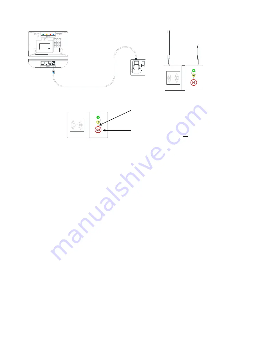
Connect
the
switch
mode
PSU
module
between
the
SUPPLY
socket
and
the
mains
supply.
Carefully
fit
the
2
aerials
by
screwing
them
into
the
2
brass
sockets
on
the
top
face.
Note:
the
longer
169MHz
aerial
must
be
on
the
left
hand
side,
the
shorter
869MHz
aerial
must
be
on
the
right.
SUPPLY
ZXT350 RANGE
Freq. 169.48125MHz
Env. Group II
Made in UK
8
5
2
0
*
1
4
7
#
3
6
9
tynetec
SMPSU MODULE (3m LEAD)
MAINS SUPPLY
DO NOT
UNPLUG
OR
SWITCH OFF
EXTENDER/REPEATER
TRANSLATOR/REPEATER
The
GREEN
and
YELLOW
buttons
are
not
used.
RED
((
))
BUTTON
Used
to
make
an
EMERGENCY
call
and
for
programming
the
unit
STATUS
LED
Steady
Green
=
Normal
or
Flashing
Green
=
Signal
Received
Flashing
Red
=
Program
Mode
Flashing
Amber
=
Mains
Supply
Failure


