


2 / 4
Isolating switch DX
3
≤
63 A
direct current, 800V
Cat. n°(s) : 4 142 21 / 23 / 24 / 26
4. PREPARATION - CONNECTION
(continued)
Supply and localisation in the installation:
Warning: isolating switches 32 A (Cat. No. 4 142 24) and 63 A (Cat.
No. 4 142 26) do not accept « reverted currents ». In a photovoltaic
installation, they cannot be installed close to solar panels to control
groups of panels but only close to the UPS to control the whole
group of panels.
Terminal depth:
. 14 mm.
. It is necessary to use the insulating shields between terminals.
. The shields are delivered with this isolating switch.
Screw head:
. Mixed, slotted and Pozidriv n° 2.
Recommended tightening torque:
. 3 Nm.
Recommended tools:
. For the terminals: screwdriver Pozidriv n°2.
. For attaching or removing the DIN rail: screwdriver slotted 5.5 mm
(6 mm maximum).
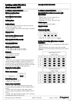
Conductor type:
Copper cable
Without ferrule
With ferrule
Rigid wire
1 x 1,5 mm² to 35 mm²
2 x 1,5 mm² to 16 mm²
-
Flexible
wire
1 x 1,5 mm² to 25 mm²
2 x 1,5 mm² to 10 mm²
1 x 1,5 mm² to 25 mm²
Manual actuation of the IS:
.
Ergonomic 2-position handle
- “O-OFF”: Device open
- “I-ON”: Device closed
Display of contacts status :
. By the position of the handle and printings
- “O-OFF”: = contacts open
- “I-ON”: = contacts closed
Sealing:
.
Possible in the open or closed positions
Locking:
. With padlock (Cat. No. 0 044 43 or 0 227 97), whit support for
padlock (Cat. No. 4 063 03) in the open position.
4. PREPARATION - CONNECTION
(continued)
Labelling:
. Circuit identification by way of a label inserted in the label holder
situated on the front of the product.
5. GENERAL CHARACTERISTICS
Marking on the front side:
.
By permanent ink pad printing - category of use DC21B.
- relevant standard n° IEC 60947-3.
- rated current in amps (A).
- rated voltage in volts (V).
- cat. n° and logo
- grand name Legrand.
- I and O with a double arrow.
- electrical diagram.
Marking on the Left side:
. By laser:
- wiring diagram
Technical data sheet : F01282EN/02
Updated : 24/08/2016
created : 7/10/2011


