


17
EN
310963 MTBS 45A
3 Installation
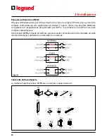
Installing the MTBS BOX
CAUTION
•
A licensed electrician must install the MTBS BOX.
•
The UPS unit must be switched off and unplugged before installation.
•
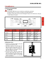
Install a utility circuit breaker for input wiring. Refer to the drawing & table below.
MODEL
Maximum
Current
Conductor
Section
Torque
force
Recommended
Breaker
4.5KVA
25 A
AWG #10
6 mm
2
17.7/11 lb-in
2/1.5 Nm
MAX 32A
Curve C
6KVA
33 A
AWG #8
10 mm
2
17.7/11 lb-in
2/1.5 Nm
MAX 32A
Curve C
8KVA
43.4 A
AWG #8
10 mm
2
23 lb-in
3 Nm
MAX 63A
Curve C
10KVA
54.3 A
AWG #6
16 mm
2
23 lb-in
3 Nm
MAX 63A
Curve C
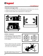
Tower Configuration
1. Place the MTBS BOX on the top rear of the
UPS unit.
2. Locate and align the fixing holes on the
MTBS BOX and UPS unit. Use a screwdriver
to fasten the fixing plates with the provided
screws and attach the MTBS BOX to the UPS
unit.
3. Place the UPS and MTBS BOX in the upright
tower position and secure the mounting
feet.(The mounting feet are provided with
the UPS or from a dealer.)
Picture 1
Содержание 310963 MTBS 45A
Страница 1: ...Part LE08105AB 12 15 01 GF 310963 MTBS 45A Manuel d installation Installation manual ...
Страница 2: ...2 FRANÇAIS 3 ENGLISH 13 ITALIANO 23 DEUTSCH 33 ESPAÑOL 43 FR FR IT DE ES EN 310963 MTBS 45A ...
Страница 12: ......
Страница 22: ......
Страница 32: ......
Страница 42: ......


