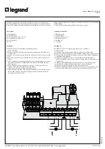
• Test
Connect the input cable to the mains power supply, a load to the UPS output
(e.g. a lamp) and the EPO (Normally Closed - NC). With the UPS switched off,
check the following:
- bypass switch in position I (yellow light on) - the load receives power;
- bypass switch in position 0 (yellow light off) - the load receives no power;
- push the EPO button and check that the UPS switches off.
Switch on the UPS and check that the load receives power when
the bypass switch is in both positions.
If this does not take place, check the connection of the cables,
the supply voltage rating and that the bypass is fully inserted into the UPS socket.
• Use of the bypass in normal operating conditions
When the UPS is operating in normal conditions, the bypass
switch must remain in position 0 and EPO contact closed.
NOTE: Never leave the bypass switch in position I during normal
UPS operation: the load is not protected in case of a mains supply
blackout because the UPS output is not connected.
• Use of the bypass for service
To disconnect the UPS:
- commute the bypass switch to position I.
- switch off the UPS.
- Unscrew the fixing screws on the bypass and then remove the bypass
from the UPS socket.
NOTE: the load now receives power directly from the mains
power supply. If the bypass switch is put to position 0, the
power supply to the load will be interrupted.
To reconnect the UPS:
- replace the bypass into the UPS socket (refer to point 8 of
the installation procedure).
- switch on the UPS.
- commute the bypass switch to position 0.
• Collaudo iniziale
Collegare il cavo di ingresso alla rete, un carico di segnalazione all’uscita
(es. una lampada) e l’EPO (Normalmente Chiuso - NC). Con UPS spento
verificare che:
- se l’interruttore è in posizione I (spia gialla accesa), il carico è alimentato;
- se l’interruttore è in posizione 0 (spia gialla spenta), il carico non è alimentato;
- premere il pulsante di EPO e verificare lo spegnimento dell’UPS.
Accendere l’UPS e verificare che, con l’interruttore in entrambe le posizioni, il carico sia
sempre alimentato. Nel caso che il comportamento non sia quello indicato, controllare
i collegamenti dei cavi, la tensione della rete di alimentazione e che la presa dell’unità
bypass sia ben inserita.
• Modo d’uso normale
Quando l’UPS viene utilizzato nel modo normale tenere l’interruttore del bypass in
posizione 0 e contatto EPO chiuso.
ATTENZIONE: Non lasciare mai l’interruttore nella posizione I durante il modo d’uso
normale, perché, in caso di interruzione dell’alimentazione da rete, l’UPS non é
collegato all’uscita.
• Modo d’uso service/manutenzione
Per scollegare l’UPS:
- Portare l’interruttore del bypass in posizione I.
- Spegnere l’UPS.
- Togliere l’unità bypass dal retro dell’UPS, togliendo prima le viti
di fissaggio. Rimuovere poi il bypass dal connettore dell’UPS.
ATTENZIONE: in questa condizione i carichi sono alimentati
direttamente da rete. Portando l’interruttore nella posizione 0 si
interrompe l’alimentazione al carico.
Per ricollegare l’UPS:
- reinserire l’unità bypass (vedi punto 8 dell’installazione).
- accendere l’UPS.
- portare l’interruttore del bypass in posizione 0.
Technical
data
3 109 77
Manual bypass
Input Voltage
184 - 265 V
Output Voltage
184 - 265 V
Input & Output current
35 A max
Max UPS power
6000 VA
Degree of Protection
IP 20
Size
240 x 145 x 59 mm
Caratteristiche
tecniche
3 109 77
Bypass manuale
Tensione d’ingresso
184 - 265 V
Tensione d’uscita
184 - 265 V
Corrente ingresso e uscita
35 A max
Massima potenza commutabile
6000 VA
Grado di protezione
IP 20
Dimensioni
240 x 145 x 59 mm


