LEGRAND 3 109 53 Скачать руководство пользователя страница 5

3 109 53  Maintenance Bypass Switch

Installa

tion M

anual

5

1.2 

Guarantee terms

The guarantee conditions may vary depending on the country where the maintenance by-

pass switch 3 109 53 is sold. Check with your local LEGRAND sale representative for validity 

and duration.

The Manufacturer declines all direct and indirect liabilities resulting from:

- failure to observe instructions included in this manual; 

- use by personnel who have not read and thoroughly understood the content of this manual; 

- use that does not comply with the specific standards used in the country where the equipment 

is installed; 

- modifications made to the equipment, software, functioning logic unless they have been author-

ized by the Manufacturer in writing; 

- repairs that have not been authorized by the LEGRAND Technical Assistance Centre; 

- damage caused intentionally, through negligence, by acts of God, natural phenomena, fire or 

liquid infiltration.

 ATTENTION 

It is necessary to read carefully these safety provisions and the entire manual before carry-

ing out any operation.

 DANGER 

This product should be installed in compliance with installation rules, preferably by a qualified 

electrician. Incorrect installation and use can lead to risk of electric shock or fire.

Before carrying out the installation, read the instructions and take account of the product’s specific 

mounting location.

Do not open up, dismantle, alter or modify the device except where specifically required to do so 

by the instructions. All Legrand products must be opened and repaired exclusively by personnel 

trained and approved by Legrand. Any  unauthorized opening or repair completely cancels all 

liabilities and the rights to replacement and guarantees.

Use only Legrand brand accessories.

 DANGER 

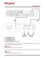
The maintenance bypass switch 3 109 53 can only be installed with the UPS Daker DK 1000 VA 

- 2000 VA - 3000 VA and Daker DK+ 1000 VA - 2000 VA - 3000 VA completely SWITCHED OFF and 

UNPLUGGED FROM THE MAINS.
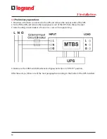
1 Introduction

2 Safety regulations

Содержание 3 109 53

Страница 1: ...Part LE09522AA 08 16 01 GF 3 109 53 Maintenance Bypass Switch Installation Manual...

Страница 2: ...2 ENGLISH 3 FR EN 3 109 53 Maintenance Bypass Switch...

Страница 3: ...gulations 5 3 Installation 7 3 1 Introduction 7 3 2 Front panel 8 3 3 Package content 9 3 4 Rack Mount Configuration 10 3 5 Tower Configuration 11 3 6 Preliminary operations 12 3 6 1 Procedure for Dak...

Страница 4: ...personnel who must have had adequate preliminary training The MTBS has been built for the applications specified in this manual For no reason whatsoever it is allowed to use it for purposes other than...

Страница 5: ...ena fire or liquid infiltration ATTENTION It is necessary to read carefully these safety provisions and the entire manual before carry ing out any operation DANGER This product should be installed in...

Страница 6: ...not use this equipment in dusty or corrosive environments or near any flammable objects The power requirement for each load connected to the maintenance bypass switch must not exceed the individual o...

Страница 7: ...ce Bypass Switch MTBS 1 UPS MODE UPS available when the MTBS works on UPS mode the UPS supply directly the loads 2 UTILITY MODE maintenance bypass when the MTBS works on the UTILITY mode the loads are...

Страница 8: ...S output sockets 2 Input Socket connect to the mains socket 3 CAM SWITCH Maintenance Bypass Switch 4 Lamps they indicate the presence of the UPS and of the mains 5 6 Load Sockets connect to the loads...

Страница 9: ...3 109 53 Maintenance Bypass Switch 9 Installation Manual 3 3 Package content 3 Installation...

Страница 10: ...10 3 Installation 3 4 Rack Mount Configuration Step 1 Step 2 Step 3...

Страница 11: ...3 109 53 Maintenance Bypass Switch 11 Installation Manual 3 5 Tower Configuration 3 Installation Step 1 Step 2...

Страница 12: ...2 Turn off the UPS and remove the input power cord of the UPS from the wall socket 3 Install a utility circuit breaker of max 20 A curve C for input wiring 4 Make sure the CAM Switch Maintenance Bypas...

Страница 13: ...Bypass Switch 13 Installation Manual 3 6 1 Procedure for Daker DK 1000 2000 VA C1 cable IEC320 C19 20 C2 cable IEC320 C15 C16 C3 cable IEC320 C19 C16 C4 cable IEC320 C20 C15 C5 power cord Schuko IEC32...

Страница 14: ...put power cord C5 to the input socket of the MTBS 2 and then to the mains socket The orange lamp of the MTBS 4 will light up DANGER Hazardous voltages are now present in the MTBS 2 Connect the cable C...

Страница 15: ...ad sockets of the MTBS 5 6 using the cables C2 and C1 or those provid ed with the UPS The loads are now supplied directly from the mains through the MTBS 5 Turn on the UPS following the instructions o...

Страница 16: ...cable C1 to the UPS output power cord of the MTBS 1 and to the output socket of the UPS 4 Make sure the loads comply with the voltage and current of the UPS and the mains If so con nect the loads to t...

Страница 17: ...pplied directly by the mains Step 3 Turn off the UPS Step 4 Remove the connection between the UPS and the MTBS Step 5 The maintenance or replacement of the UPS may now proceed 2 UTILITY MODE Maintenan...

Страница 18: ...contact a qualified electrician The input power cord connected to the input socket of the MTBS 2 is not connected properly to the mains socket Connect it to the mains socket Green lamp of the UPS is...

Страница 19: ...ature range 32 F to 104 F 0 C to 40 C Operating relative humidity range 20 80 non condensing Storage temperature range 4 F to 104 F 20 C to 40 C Operating altitude up to 6560 ft 2000m Electrical speci...

Страница 20: ...droit de modifier tout moment le contenu de cet imprim et de communiquer sous n importe quelle forme et modalit les changements apport s LEGRAND Pro and Consumer Service BP 30076 87002 LIMOGES CEDEX F...

Отзывы: