background image

Installation and Startup Guide

Rio Rancho, NM

13

Using the LCD

The LCD can be used to perform a simple setup, to 

check current settings or make adjustments without us-

ing a computer interface.
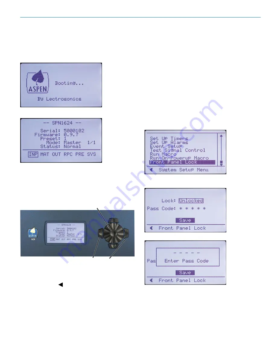
Boot Screen

Main Window

Navigation Control

The navigation control for the LCD consists of a rotary 

control and four directional buttons for selection of 

menu items and to enter values. The four outer buttons 

are referenced as LEFT, RIGHT, UP and DOWN. Press-

ing the center of the rotary control provides a “select” or 

“center switch” function.

Press both Left and Right buttons to 

turn the LCD backlight OFF and ON

Center Switch

The LEFT (9:00 o’clock) functions as a BACK button 

to return to the previous menu from setup screens as 

prompted by the   symbol in the lower left corner of 

the LCD.

Shortcut Buttons

•  LCD Backlight Toggle:  Press both the LEFT and 

RIGHT (9:00 and 3:00 o’clock) buttons to turn the 

backlight on and off.

•  Emergency Mute (panic button):  Pressing the UP 

and DOWN buttons together will mute all outputs to 

remedy situations such as runaway feedback.

•  Restore Default Settings (Master Reset):  Hold 

in the LEFT and UP buttons while turning on the 

power to restore the factory default settings. The 

Alert LED will glow white during the process, which 

takes about 75 seconds to complete.

Panel Lock/Unlock

From the Main Window, use the rotary control to select 

SYS

 in the lower row window and press the center 

switch. Then scroll down with the rotary control to the 

menu item named 

Front Panel Lock

 and press the cen-

ter switch to enter the setup screen.

Select the 

Unlocked/Locked

 item with the rotary control, 

press the center switch.

A prompt will appear asking you to enter the passcode.

The factory default passcode is five presses of the cen-

ter switch. Once the correct passcode is entered, the 

panel will allow access to the screen items to change 

the unlocked/locked status, enter a new passcode and 

save the results.
The passcode can consist of any combination of five 

successive button presses of the four outer switches 

and the center switch such as:  LEFT > RIGHT > UP > 

DOWN > CENTER.

Содержание SPN1612

Страница 1: ...onics com Fill in for your records Serial Number Purchase Date This manual covers the following models SPN2412 SPN1624 SPN1612 SPN812 See Quick Start Essential Settings on page 6 Visit the Lectrosonic...

Страница 2: ...SPN Mixers LECTROSONICS INC 2...

Страница 3: ...fied by the manufacturer 12 Use only with the cart stand tripod bracket or table specified by the manufacturer or sold with the apparatus When a cart is used use caution when moving the cart apparatus...

Страница 4: ...This equipment has been tested and found to comply with the limits for a Class A digital device pursuant to Part 15 of the FCC Rules These limits are designed to provide reasonable protection against...

Страница 5: ...7 Rear Panels 8 Hardware Installation 10 Installing the chassis into a rack 10 Cables 10 Audio Connectors 10 Audio Inputs Unbalanced 10 Audio Outputs 11 Programmable Inputs 11 Programmable Outputs 11...

Страница 6: ...aster so a single connection between a computer and the Master allows access to all units in the stack The throughput latency of all audio inputs in a stack is automatically synchronized to maintain a...

Страница 7: ...he setup and control of a DMTH4 from an Windows XP Vista or 7 computer system with USB interface Status LEDs Comm LED blinks to indicate USB RS 232 and ether net communication Alert LED blinks to indi...

Страница 8: ...onitoring setup and control Power Inlet RS232 Serial Port Programmable Input and Output Ports ASPEN Ports Balanced Inputs Cooling Fan Outlet Ethernet Port Balanced Outputs Balanced Inputs Balanced Out...

Страница 9: ...TS GND 5V PROG IN PROG OUT GND PROG IN 5V PROG OUT Adaptive Proportional Gain Mixing US Patent 5 414 776 S N LABEL DATECODE Made In the USA SPN1612 SPN2412 100 240V 50 60Hz 40W ASPEN PORTS ETHERNET RS...

Страница 10: ...nt damage to the front panel s finish when tightening the mounting screws All ASPEN processors have internal switching power supplies that can tolerate voltages ranging from 100 to 240 VAC Use an appr...

Страница 11: ...is active it conducts current to ground When the programmable output is inactive no current flows to ground The maximum usable voltage for the pro grammable outputs is 40 V and they will safely conduc...

Страница 12: ...r Male connector Female jack Male jack Cabling Of Stacked Units In a stacked configuration ASPEN processors must be interconnected as shown here Each Slave unit in a stack gathers data and audio signa...

Страница 13: ...n Pressing the UP and DOWN buttons together will mute all outputs to remedy situations such as runaway feedback Restore Default Settings Master Reset Hold in the LEFT and UP buttons while turning on t...

Страница 14: ...the Main Window and the right blue LED will light up to indicate power ON and a ready status Initial Setup The processor requires a minimum setup before it will pass signals Input Gain Value Crosspoi...

Страница 15: ...refinements can be added with the extensive set of signal processing built into the processor Browse the menus for inputs and outputs to discover the available resources Rear Panel Controls Select RP...

Страница 16: ...ft ware and to see that the hardware includes the latest firmware ASPEN models with a front panel LCD will display the firmware version on the LCD and in the control panel GUI after the software is in...

Страница 17: ...he processor The unit will boot into the Firmware Update mode and the white Alert LED on the processor front panel will glow Recessed pushbutton for firmware updates 4 Connect the processor to the com...

Страница 18: ...sh drive then follow the steps to begin the installation 1 Navigate to the USB drive folder and click on the Control Panel folder 2 Click on setup 3 Click on Yes to allow the program to make changes t...

Страница 19: ...ion in this example USB Click OK in the Master unit discovery popup window This popup will appear with the Master unit displayed The left side of the control panel will appear with a list of processor...

Страница 20: ...he control panel The Master unit will appear at the top of the stack with Slave units below it appear ing in the order that they are connected with the cable connections to the ASPEN port jacks List o...

Страница 21: ...Returning Units for Repair For timely service please follow the steps below A DO NOT return equipment to the factory for repair without first contacting us by e mail or by phone We need to know the n...

Страница 22: ...SPN Mixers LECTROSONICS INC 22...

Страница 23: ...Installation and Startup Guide Rio Rancho NM 23...

Страница 24: ...osonics Inc will pay for the cost of returning your equipment to you This warranty applies only to items returned to Lectrosonics Inc or an authorized dealer shipping costs prepaid within three years...

Отзывы: