Lectrosonics SMa Series Скачать руководство пользователя страница 5

Super-Minature Belt Pack Transmitters 

Low Frequency Roll-Off 

The low frequency roll-off can be set for a 3 dB down 

point at 35, 50, 70, 100, 120 and 150 Hz to control sub­

sonic and very low frequency audio content in the au­

dio. The actual roll-off frequency will vary slightly depend­

ing upon the low frequency response of the microphone. 
Excessive low frequency content can drive the transmit­

ter into limiting, or in the case of high level sound sys­

tems, can even cause damage to loudspeaker systems. 

The roll-off is normally adjusted by ear while listening 

as the system is operating. 

Input Limiter 

A DSP-controlled analog audio limiter is employed before 

the analog-to-digital (A-D) converter. The limiter has a range 

of more than 30 dB for excellent overload protection. A dual 

release envelope makes the limiter acoustically transparent 

while maintaining low distortion. It can be thought of as two 

limiters in series, a fast attack and release limiter followed by 

a slow attack and release limiter. The limiter recovers quickly 

from brief transients, with no audible side effects, and also 

recovers slowly from sustained high levels, to keep audio 

distortion low and while preserving short term dynamics. 

Signal Encoding and Pilot Tone 

In addition to controlling the limiter, the DSP also en­

codes the digitized audio from the A-D converter and 

adds an ultrasonic pilot tone to control the receiver’s 

squelch. A pilot tone squelch system provides a reliable 

method of keeping a receiver output muted (squelched) 

even in the presence of significant interference. When 

the system is operating in the hybrid mode, a differ­

ent pilot tone frequency is generated for each carrier 

frequency to prevent inadvertent squelch problems and 

simplify multi-channel coordination. 

Microprocessor, PLL and VCO Circuits 

A microprocessor monitors user command inputs from 

the control panel buttons and numerous other internal 

signals. It works intimately with the DSP to ensure the 

audio is encoded according to the selected Compatibil­

ity Mode and that the correct pilot tone is added to the 

encoded signal. 

Compatibility Modes 

The SM transmitters were designed to operate with 

Lectrosonics Digital Hybrid receivers and will yield the 

best performance when doing so. However, due to the 

flexibility of digital signal processing, the transmitters 

can also operate in various compatibility modes for use 

with Lectrosonics 200 Series, Lectrosonics 100 Series, 

IFB and certain non-Lectrosonics receivers. Contact 

the Lectrosonics sales department for a complete list of 

compatible non-Lectrosonics receivers. 

Control Panel 

The control panel includes four membrane switches and 

an LCD screen to adjust the operational settings. Multi-

color LEDs are used to indicate audio signal levels for 

accurate gain adjustment and for battery status. 

Wide-Band Deviation 

±75 kHz deviation improves the signal to noise ratio and 

audio dynamic range of a wireless system dramatically, 

compared to other designs that use ±30 kHz to 40 kHz 

deviation. Wide deviation combined with a high powered 

transmitters makes a significant improvement in signal 

to noise ratio and operating range. 

Battery Options and Operating Time 

Switching power supplies convert regulated battery 

voltages to operate various circuit stages with maxi­

mum efficiency. With the variety of alkaline, lithium and 

rechargeable NiMH batteries available today in the AA 

format, there are many choices to maximize operating 

time or minimize cost as needed for any application. 

Frequency Blocks 

Lectrosonics established a “block” numbering system 

years ago to organize the range of frequencies avail­

able from the low 500 MHz band to the upper 700 

MHz band. Each block includes 256 frequencies in 100 

kHz increments. The block number is part of a simple 

formula to derive the frequency. The block number is 

multiplied by 25.6 to produce the lowest frequency in 

the block. For example, block 27 x 25.6 = 691.200. 

Circulator/Isolator 

The RF output circuit includes a one way circulator/isolator 

using a magnetically polarized ferrite. This device greatly 

reduces the RF intermodulation produced when multiple 

transmitters are used in close proximity to one another 

(several feet apart). The isolator also provides additional 

RF output stage protection. 

Rio Rancho, NM 

5


Содержание SMa Series

Страница 1: ...e Belt Pack Transmitters With Digital Hybrid Wireless Technology SMa Single battery 100 mW RM Remote Control Digital Hybrid Wireless US Patent 7 225 135 Fill in for your records Serial Number Purchase...

Страница 2: ...SMa Series LECTROSONICS INC 2...

Страница 3: ...d perspiration in extreme envi ronments Table of Contents General Technical Description 4 Controls and Functions 6 LCD Screen 6 Power LED 6 Audio Input Jack 6 Battery Compartment and Thumb Screw 6 Mod...

Страница 4: ...defeat the noise by sending the audio information in digital form at the cost of some combination of power bandwidth and resistance to interference US Patent 7 225 135 Lectrosonics Digital Hybrid Wire...

Страница 5: ...correct pilot tone is added to the encoded signal Compatibility Modes The SM transmitters were designed to operate with Lectrosonics Digital Hybrid receivers and will yield the best performance when d...

Страница 6: ...or secure the Battery Compartment Cover Plate allowing access to the battery Modulation LEDs The Modulation LEDs provide a visual indication of the input audio signal level from the microphone These t...

Страница 7: ...ing and holding the AUDIO and FREQ buttons displays a timer with numerals on the right The numerals count up from one and the boot sequence begins when the count reaches three LECtro is displayed as t...

Страница 8: ...ailable from the remote control are Audio Level Frequency Lock Unlock Buttons Sleep Wake power saving mode In sleep mode the SM uses 20 of the normal amount of current For example in sleep mode it wil...

Страница 9: ...imultaneously to enter and exit this mode Selecting the Compatibility Mode 400 Series or Digital All Digital Hybrid Wireless Hybrid Wireless receivers are capable of work compatibility mode ing with t...

Страница 10: ...n The control panel Modulation LEDs indicate the modu lation level and limiter activity Once set the transmit ter s audio level setting should not be used to control the volume of your sound system or...

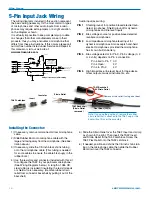
Страница 11: ...cked mode Attaching and Removing the Microphone The flexible sleeve over the 5 pin plug on the micro phone helps prevent dust and moisture from getting into the input jack A flange is machined into th...

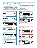
Страница 12: ...o Limiter Control LINE IN PIN 5 High impedance line level input for tape decks 3 3uF mixer outputs musical instruments etc SM Equivalent Input Circuit Wiring 10k 2 7K TA5F Latchlock Insert Insulator S...

Страница 13: ...lamp the insulation Strip and position the cable so that the clamp can be crimped to contact both the mic cable shield and the insulation The shield contact reduces noise with some microphones and the...

Страница 14: ...ling RF bypass capacitors at the mic capsule If this is not pos sible or if you are still having problems capacitors can be installed on the mic pins inside the TA5F connector housing 2 WIRE MIC 3 WIR...

Страница 15: ...e inserted in series with Pin 5 for an additional 20 dB of attenuation to handle up to 30V 32 dBu Fig 8 1 2 3 4 5 PIN SHIELD AUDIO 1 2 3 4 5 TA5F PLUG 2 7 k 2 VOLT NEGATIVE BIAS 2 WIRE ELECTRET Compat...

Страница 16: ...interface is organized into pages which are accessible via the AUDIO and FREQ buttons Once on a page settings can be adjusted with the UP and DOWN arrow buttons To change a transmitter s setting via...

Страница 17: ...attempt is made to set the transmitter s frequency in MHz the command will still work The transmitter is simply set to the corresponding channel in the correct block with a matching hex code Since al...

Страница 18: ...ches display on transmitter and receiver 5 Transmitter and receiver not on same frequency block 6 Operating range is too great 7 Defective transmitter antenna unit needs repair NO SOUND OR LOW SOUND L...

Страница 19: ...en the unlocked condition was indicated TRANSMITTER WON T RESPOND TO REMOTE CONTROL 1 If LCD blinks rc oFF transmitter has not be configured to respond to the remote control See Remote Control Operati...

Страница 20: ...k of unit as pictured SMBCUPSL Spring loaded machined aluminum clip Antenna and mic connector will face up 35923 Thermal insulated pad installed on SMa PSM Leather pouch with integrated belt clip Plac...

Страница 21: ...RF exposure using this product This device complies with FCC radiation exposure limits as set forth for an uncontrolled environment This device should be installed and operated so that its antenna s...

Страница 22: ...for Repair For timely service please follow the steps below A DO NOT return equipment to the factory for repair without first contacting us by email or by phone We need to know the nature of the probl...

Страница 23: ...Super Minature Belt Pack Transmitters Rio Rancho NM 23...

Страница 24: ...aler shipping costs prepaid within one year from the date of purchase This Limited Warranty is governed by the laws of the State of New Mexico It states the entire liablility of Lectrosonics Inc and t...

Отзывы: