4PSXXIVXIWXW
%P]WQEMRXIRERGIQERYEP
%%
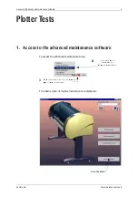
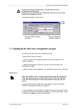
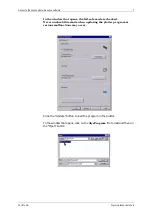
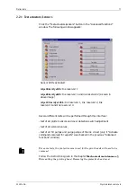
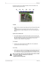
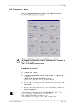
Doing so will allow you to monitor the status of the LEDs visible on the
heads command electronics board.
'IPP[MHXL
1.
Place / remove one sheet of paper between the print head and the plotter
beam.
The
'
LED on the “head board” and the LED visible in the “Test
actuators/sensors” window displayed on the screen should change their
status.
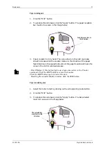
3TXMGEPJSVO^IVSHIXIGXMSRGIPP
1.
Move head completely to the left of the plotter (on the same side as the
command keyboard). When the head is almost at the end, the head board
'
LED should change status. The LED displayed in the control
window on screen should also change status.
0MRIEVIRGSHIV
1.
Carefully move the head by hand. The
'
LED on the head board
should flash while the head is moving.
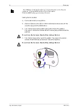
'SZIVGPSWIH
1.
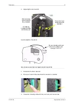
When the cover is closed, the LED displayed on the control screen should
be on. Opening the cover only 4 centimeters should make this LED go
out. If this does not happen,
\RXPXVW
adjust the cover detection switch.
!
7KHFRYHUGHWHFWLRQFHOOLVDQH[WUHPHO\LPSRUWDQWVHFXULW\HOHPHQW
IRUWKHSORWWHU,PSURSHUDGMXVWPHQWFDQSURYRNH
DVHFXULW\PDOIXQFWLRQ
FRPSOHWHVHL]XUHRIWKHSORWWHU
'
'
'
'
'
'
Содержание Alys 120
Страница 4: ...MZ P W QEMRXIRERGI QERYEP ...
Страница 10: ... ERHPMRK ERH WXSVEKI SJ GSRWYQEFPI MXIQW P W QEMRXIRERGI QERYEP ...
Страница 72: ... ERHPMRK P W QEMRXIRERGI QERYEP ...

