background image

Operator's Manual 

WSta-OM-E RevA 

15 

2.


USB Connector

 - USB 2.0 connector which is used for making 

USBRAW

 or 

USBTMC

 connections as explained in 

WaveStation PC 

Software Overview

 (on page 78) and 

Controlling WaveStation 

with USB-GPIB and/or USBTMC

 (on page 76), respectively. 

3.


Ground Connector


4.


AC Power Connector


Getting Started with WaveStation 

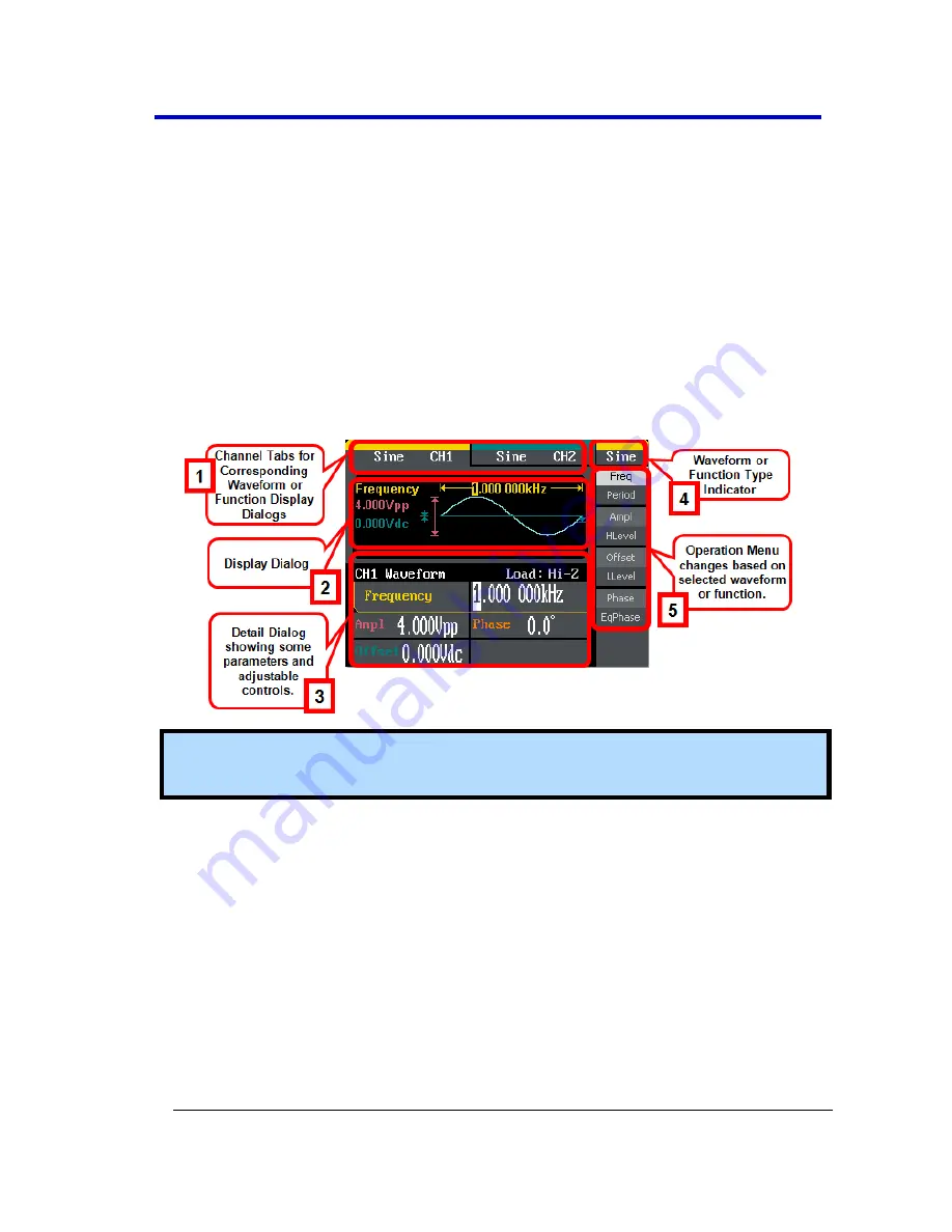
The WaveStation Interface 

Numbered callouts on this image of the WaveStation interface 
correspond with the following descriptions. 


Note

: The default signal is a 

Sine

 wave as each channel tab and in the 

upper-right corner of the display show. 

1.


Channel Tabs

 - The channel tabs display the currently chosen 

Waveform

 or 

Function

 type and, when selected, show their 

corresponding 

Display

 and 

Detail

 dialog. 

2.


Display Dialog

 - Shows a rendered waveform or modulated 

waveform display of your generated signal and some additional 
waveform details . 

3.


Detail Dialog

 - Shows even more data regarding specific 

parameters for your selected Waveform or Function. 

4.


Waveform/Function Type Indicator

 - When using the 

Waveform


buttons, shows the waveform type for the corresponding 
waveform channel selected. 

Содержание WaveStation 2012

Страница 1: ...Operator s Manual WaveStation Function Arbitrary Waveform Generator ...

Страница 2: ...WaveStation Function Arbitrary Waveform Generator March 2012 ...

Страница 3: ...plies Furthermore LeCroy shall not be obligated to service a product that has been modified or integrated where the modification or integration increases the task duration or difficulty of servicing the instrument Spare and replacement parts and repairs all have a 90 day warranty The instrument firmware has been thoroughly tested and is presumed to be functional Nevertheless it is supplied without...

Страница 4: ......

Страница 5: ...bnormal Conditions 11 Hardware and I O 12 Adjusting the Handle 12 Front Panel 13 Back Panel 14 Getting Started with WaveStation 15 The WaveStation Interface 15 Waveform Types and Default Parameters 21 Initial Function Settings 22 Waveform Signal Conditioning Buttons 22 Save Recall Utility and Help Buttons 23 Main Waveform Buttons 23 Waveform Signal Conditioning Function Buttons 23 Save Recall Util...

Страница 6: ...4 Creating a Pulse Wave 34 PulWidth Duty 35 Delay 36 Creating a Noise Wave 36 Variance Mean 37 Creating an Arbitrary Waveform 37 Load Wform 38 Generating Modulated Waveforms 41 Generating Sweep Waveforms 47 Generating Burst Waveforms 51 Save Recall 56 Save Recall Overview 56 Main Save Recall Operations 57 Operation Menu Selections and Parameters 58 Utility 62 Utility Overview 62 Main Utility Opera...

Страница 7: ...The USB GPIB Adapter 76 Connecting Your Adapter 77 WaveStation PC Software 78 WaveStation PC Software Overview 78 Installing the WaveStation PC Drivers and Software 79 Making the WaveStation PC Software Connection 80 Reference 89 Specifications 89 CERTIFICATIONS 89 CE Declaration of Conformity 89 China RoHS Compliance 91 China RoHS Compliance English Version 92 Contact LeCroy for Support 93 Index ...

Страница 8: ...ce and a general overview of the standard controls on the front panel and how they correspond with the screen displays 3 Sections then provide more detail covering the creation of Waveform Types Modulated Waveforms Sweep Waveforms and Burst Waveforms Additional sections explain how to use Save Recall Utility and Help sections 4 Another section explains how to Control WaveStation with USB GPIB usin...

Страница 9: ...nual WSta OM E RevA 7 Thank You We truly hope these materials provide increased comprehension when using LeCroy s fine products Sincerely David C Graef LeCroy Corporation Vice President and Chief Technology Officer ...

Страница 10: ...s information and warnings that must be observed to keep the instrument operating in a correct and safe condition You are required to follow generally accepted safety procedures in addition to the safety precautions specified in this section Safety Symbols Where the following symbols appear on the instrument s front or rear panels or in this manual they alert you to important safety considerations...

Страница 11: ...nt CAUTION The CAUTION sign indicates a potential hazard It calls attention to a procedure practice or condition which if not followed could possibly cause damage to equipment If a CAUTION is indicated do not proceed until its conditions are fully understood and met WARNING The WARNING sign indicates a potential hazard It calls attention to a procedure practice or condition which if not followed c...

Страница 12: ...ment Before using this product ensure that its operating environment is maintained within these parameters Temperature 0 C to 40 C Humidity Maximum relative humidity 80 non condensing for temperatures up to 30 C decreasing linearly to 50 relative humidity at 40 C Altitude Up to 10 000 ft 3 048 m at or below 30 C Note Direct sunlight radiators and other heat sources should be taken into account whe...

Страница 13: ...ic AC voltage selection No manual voltage selection is required because the instrument automatically adapts to line voltage Power Consumption 50 VA 50 W Max WARNING Electrical Shock Hazard Only use the power cord provided with your instrument Calibration The recommended calibration interval is one year Calibration should be performed by qualified personnel only Cleaning Clean only the exterior of ...

Страница 14: ...resses Proper use of the instrument depends on careful reading of all instructions and labels WARNING Any use of the instrument in a manner not specified by the manufacturer may impair the instrument s safety protection Hardware and I O Adjusting the Handle The construction of the handle on your WaveStation can be adjusted to bridge the front panel and fully support the weight of the generator dur...

Страница 15: ...tor which is used for making USB GPIB or Memory Stick connections as explained in Controlling WaveStation with USB GPIB and or USBTMC on page 76 and Main Save Recall Operations on page 57 respectively 3 LCD Display 4 Display Menu Operation Buttons 5 Waveform Buttons These buttons control the selection of Waveform Types and Default Parameters on page 21 6 Number Buttons 7 Function Buttons When pres...

Страница 16: ...tivation deactivation of corresponding channel outputs 9 Direction Buttons 10 Adjustment Control Knob Note When using WaveStation or any signal generator it s important to understand the relationship between the Main Waveform Type buttons the Waveform Signal Conditioning function buttons and the Save Recall Utility and Help function buttons See Combined Use of Waveform Function and Configuration B...

Страница 17: ...escriptions Note The default signal is a Sine wave as each channel tab and in the upper right corner of the display show 1 Channel Tabs The channel tabs display the currently chosen Waveform or Function type and when selected show their corresponding Display and Detail dialog 2 Display Dialog Shows a rendered waveform or modulated waveform display of your generated signal and some additional wavef...

Страница 18: ...set using certain options available from the Utility menu Learn more in Main Utility Operations on page 62 Subsequent sections go into more detail when using specific Waveform and Function buttons and adjusting specific parameters all of which vary based on the specific waveform function and or carrier waveform selections made This particular topic covers some common navigation parameter adjustmen...

Страница 19: ...s and button type combinations First Second Press Shared Buttons A good portion of the operation buttons control two separate parameters Operation buttons controlling two parameters have additional lighter shaded control labels on them press the button once to adjust the top control parameter twice to adjust the bottom one Second operation button press parameters are shown in reverse color on some...

Страница 20: ...ows Additional Menus Operation menus containing more parameters than the ones showing on the first menu have a 1 X final selection The additional menu s therefore have a 2 X first selection Press the adjacent operation button to navigate additional menu s and parameter s as desired 3 Making the actual parameter adjustments or other selection is made a few different ways Most are done by selecting ...

Страница 21: ...again to preserve the adjustment selection The only variation includes where the interface shows the adjustment selection choices Inside the Operation Menu Some adjustment selection choices are shown right on the Operation menu On the Display Dialog Some adjustment selection choices are shown right on the Display dialog ...

Страница 22: ... Detail Dialog Some adjustment selection choices are shown right on the Detail dialog On the Browser Display Dialog Some interfaces are provided using file explorer like screens for saving and recalling a variety of folders and file types ...

Страница 23: ...set The WaveStation can produce 1 μHz up to 50 MHz WaveStation 2052 Sine waves 2 Square The default Square waveform is set to 1 kHz frequency 4 0 Vpp amplitude 0V dc offset with a 50 duty cycle The WaveStation can produce 1 μHz to 25 MHz with variable duty cycle Square waves 3 Ramp The default Ramp waveform is set to 1 kHz frequency 4 0 Vpp amplitude 0V dc offset with a 50 symmetry The WaveStation...

Страница 24: ...the Main Waveform Type buttons the Waveform Signal Conditioning function buttons and the Save Recall Utility and Help function buttons See Combined Use of Waveform Function and Configuration Buttons on page 23 Select a function by pressing the corresponding function button on the Front Panel on page 13 Waveform Signal Conditioning Buttons Modulate Press the Mod button and the modulated waveforms y...

Страница 25: ... Interface Settings and to View System Setting Information Help Press the Help button and the WaveStation help system is pertaining to the current function or operation is shown Combined Use of Waveform Function and Configuration Buttons When using WaveStation or any signal generator it s important to understand the relationship between the Main Waveform Type buttons the Waveform Signal Conditioni...

Страница 26: ...d waveform Therefore a second press of the Mod Sweep or Burst button turns the LED and function off to reveal the originally selected waveform type menu The menu behavior relationship looks like the following Save Recall Utility and Help Function Buttons Also mentioned in Initial Function Settings on page 22 while the waveform type and an optional signal conditioning function is or is not applied ...

Страница 27: ...onding menu is shown Similar to Mod Sweep or Burst these buttons are optional and a second press turns off their corresponding LED and function to reveal either the the Mod Sweep or Burst menu if applied to the selected waveform otherwise the selected waveform type menu is shown The menu behavior relationship looks like the following ...

Страница 28: ...WaveStation 26 WSta OM E RevA ...

Страница 29: ...tton to more the cursor backward and delete or change values entered using the number buttons 3 The Adjustment Control Knob allows you to decrease increase more precise value increments for a selected parameter or select items from listings when by turning the knob counterclockwise clockwise respectively Creating Waveforms Creating Waveforms Overview The first step in creating your waveform is to ...

Страница 30: ...lay and Detail dialogs Press adjacent Operation buttons and use the Digital Input Front Panel Controls on page 27 to make specific adjustment selection parameter choices For more information on getting to this point see Navigating Interfaces Adjusting Parameters and Making Selections on page 16 Sine Operation menu selections and parameters include Frequency Period Amplitude HLevel Offset LLevel Ph...

Страница 31: ...plicable unit s are shown on the Operation menu Press an adjacent Operation button to select a desired Unit for your entry Provide your desired Frequency or Period using the Digital Input Front Panel Controls on page 27 Amplitude HLevel With the Sine waveform and the Amplitude HLevel operation button pressed once a Sine waveform is shown on the Waveform Display and Amplitude is shown on the Wavefo...

Страница 32: ...he Digital Input Front Panel Controls on page 27 Offset LLevel With the Sine waveform and the Offset LLevel operation button pressed once to select Offset a Sine waveform is shown on the Waveform Display and the Offset is shown on the Waveform Detail dialog PLEASE NOTE THE FOLLOWING Press the Offset LLevel operation button a second time to select and adjust the LLevel Low Level parameter in the sa...

Страница 33: ...se parameter in the same manner Second operation button press parameters are shown in reverse color on the waveform detail dialog to provide a visual indication as to which parameter is being adjusted While editing certain parameters using the Number Buttons applicable unit s are shown on the Operation menu Press an adjacent Operation button to select a desired Unit for your entry Provide your des...

Страница 34: ...rameters include Frequency Period Amplitude HLevel Offset LLevel Phase and Duty Cycle The parameters for Frequency Period Amplitude HLevel Offset LLevel Phase are carried out the same way as done when Creating a Sine Wave on page 28 Setting the Duty Cycle is done as follows Duty Cycle With the Square waveform and the Duty Duty Cycle operation button pressed a Square waveform is shown on the Wavefo...

Страница 35: ...menu and corresponding Display and Detail dialogs Press adjacent Operation buttons and use the Digital Input Front Panel Controls on page 27 to make specific adjustment selection parameter choices For more information on getting to this point see Navigating Interfaces Adjusting Parameters and Making Selections on page 16 Note Ramp Operation menu selections and parameters include Frequency Period A...

Страница 36: ...to select a desired Unit unit interval for your entry Provide your desired Symmetry amount using the Digital Input Front Panel Controls on page 27 Creating a Pulse Wave When first pressing this waveform button on the Front Panel the WaveStation shows the Pulse Operation menu and corresponding Display and Detail dialogs Press adjacent Operation buttons and use the Digital Input Front Panel Controls...

Страница 37: ...ave on page 28 Setting the PulWidth Duty Pulse Width and Delay is done as follows PulWidth Duty With the Pulse waveform and the PulWidth Duty operation button pressed once to select PulWidth a Pulse waveform is shown on the Waveform Display and the Pulse Width is shown on the Waveform Detail dialog Positive Pulse Width is the time from the first rising edge to the first falling edge Similar for Ne...

Страница 38: ...e your desired Delay amount using the Digital Input Front Panel Controls on page 27 Creating a Noise Wave When first pressing this waveform button on the Front Panel the WaveStation shows the Noise Operation menu and corresponding Display and Detail dialogs Press adjacent Operation buttons and use the Digital Input Front Panel Controls on page 27 to make specific adjustment selection parameter cho...

Страница 39: ...lect and adjust the Mean parameter in the same manner While editing certain parameters using the Number Buttons applicable unit s are shown on the Operation menu Press an adjacent Operation button to select a desired Unit for your entry Provide your desired Variance or Mean values using the Digital Input Front Panel Controls on page 27 Creating an Arbitrary Waveform When first pressing this wavefo...

Страница 40: ...uency Period Amplitude HLevel Offset LLevel and Phase EqPhase are carried out the same way as done when Creating a Sine Wave on page 28 Operation menus containing more parameters than the ones showing on the first menu have a 1 X final selection The additional menu s therefore have a 2 X first selection Press the adjacent button to navigate additional menu s and parameter s as desired Loading a St...

Страница 41: ...d UpRamp and DnRamp Math Math Built In Arbitrary Waveforms include ExpFall Exponential Fall ExpRise LogFall Logarithmic Fall LogRise Sqrt Square Root Root3 X 2 X 3 Sinc Gaussian Dlorentz D Lorentz Haversin Haversine Lorentz Gauspuls Gaussian modulated sinusoidal pulse Gmonpuls Gaussian monopulse and Tripuls triangle pulse Project Project Built In Arbitrary Waveforms include Cardiac electrocardiogr...

Страница 42: ...d Waveforms are shown on the Waveform Display dialog as follows Note Select the stored waveforms showing on the Waveform Display dialog using the Digital Input Front Panel Controls on page 27 specifically the Direction Buttons or the Control Knob Make your selection by pressing the Select option button ...

Страница 43: ...uttons and the Save Recall Utility and Help function buttons See Combined Use of Waveform Function and Configuration Buttons on page 23 Default values for many controls can be set using certain options available on the Utility menu Learn more in Main Utility Operations on page 62 This section covers details around creating modulated waveforms and making specific adjustment selection parameter choi...

Страница 44: ...f the user set amplitude value When set to 0 the output amplitude is approximately half of the user set amplitude value When set to 100 the output amplitude matches the amplitude set When using an external source the AM depth is controlled by the voltage level of the connector attached to Modulation In on the Back Panel on page 14 6V corresponds to 100 of your current depth setting Type Amplitude ...

Страница 45: ...f the selected waveform When using an external source the deviation is controlled by the voltage level of the connector attached to Modulation In on the Back Panel on page 14 6V corresponds to the selected deviation and 6V to the negative selected deviation So a 6 V input results in an output FM deviation equal to the preset FM deviation Type Frequency modulation Shape Choose the waveform shape ty...

Страница 46: ...carrier wave The amplitude of an analog carrier signal varies in accordance with the bit stream modulating signal keeping frequency and phase constant Mod ASK Operation menu selections and parameters include Key Freq Type and Source as follows Key Freq This parameter sets the frequency at which the output amplitude shifts between the carrier amplitude and 0 The internal source frequency range is 2...

Страница 47: ...erfaces Adjusting Parameters and Making Selections on page 16 FSK modulation is an output frequency that switches from the carrier waveform and hop preset frequencies at a specific point The specific frequency point where the output switches is the Key Frequency The Key Frequency is determined by the internal frequency generator or the signal voltage level from the Trig Gate Fsk Burstconnector on ...

Страница 48: ... Generating Modulated Waveforms Overview on page 41 the WaveStation shows the PM Operation menu and corresponding Display and Detail dialogs Press adjacent Operation buttons and use the Digital Input Front Panel Controls on page 27 to make specific adjustment selection parameter choices For more information on getting to this point see Navigating Interfaces Adjusting Parameters and Making Selectio...

Страница 49: ...Panel on page 14 Generating Sweep Waveforms Specific waveform types may be swept as carrier waveforms using the WaveStation Sine Square Ramp or Arb waveforms may be swept while Pulse Noise and DC cannot Frequency sweep mode uses the WaveStation to sweep from the start frequency to the stop frequency at a specified sweep rate The first step in creating a sweep waveform is to press the Sweep button ...

Страница 50: ...ep button on the Front Panel on page 13 select the desired modulated waveform type using the Display Menu Operation buttons The waveform is shown on the Waveform Display At this point the Display Menu Operation buttons are used to select applicable parameters and make adjustments as desired A good portion of the waveform operation buttons control two separate parameters Operation buttons controlli...

Страница 51: ... displays the particular parameter selection Operation menus containing more parameters than the ones showing on the first menu have a 1 X final selection The additional menu s therefore have a 2 X first selection Press the adjacent button to navigate additional menu s and parameter s as desired Frequency sweep mode uses the WaveStation to sweep from the start frequency to the stop frequency at a ...

Страница 52: ...om specified start frequency to stop frequency values StopFreq Provide a specific frequency value where the sweep must end FreqSpan Provide an overall span or range in which the sweep must remain StartFreq Provide a specific frequency value where the sweep is to begin MidFreq Specify a frequency where the center of the sweep must remain Source Select Internal External or Manual If External is sele...

Страница 53: ... relationship between the Main Waveform Type buttons the Waveform Signal Conditioning function buttons and the Save Recall Utility and Help function buttons See Combined Use of Waveform Function and Configuration Buttons on page 23 Default values for many controls can be set using certain options available on the Utility menu Learn more in Main Utility Operations on page 62 This section covers bur...

Страница 54: ...s and make adjustments as desired A good portion of the waveform operation buttons control two separate parameters Operation buttons controlling two parameters have additional lighter shaded function labels on them press the button once to adjust the top control parameter twice to adjust the bottom one Make adjustments using the Digital Input Front Panel Controls on page 27 Second operation button...

Страница 55: ...e particular parameter selection Operation menus containing more parameters than the ones showing on the first menu have a 1 X final selection The additional menu s therefore have a 2 X first selection Press the adjacent button to navigate additional menu s and parameter s as desired Press adjacent Operation buttons and use the Digital Input Front Panel Controls on page 27 to make specific adjustm...

Страница 56: ... change based on the selection made on this control When NCycle is selected you can press the Period operation button and provide a specific value for the Pulse Period control using the detail dialog Note The period time increases if necessary to allow the specified number of cycles in a burst The following formula is applied to the logic of this control Burst Period Carrier Period Burst Number N ...

Страница 57: ...time increases if necessary to allow the specified number of cycles in a burst as previously mentioned in the NCycle Gated bullet An external or manual trigger is required in order to activate an infinite burst Delay This control is only available when NCycle is selected from the third operation button With Delay selected you can specify a span of time between the trigger input and the start of th...

Страница 58: ...een PLEASE NOTE THE FOLLOWING When using WaveStation or any signal generator it s important to understand the relationship between the Main Waveform Type buttons the Waveform Signal Conditioning function buttons and the Save Recall Utility and Help function buttons See Combined Use of Waveform Function and Configuration Buttons on page 23 Default values for many controls can be set using certain o...

Страница 59: ...le display dialog which is used with Digital Input Front Panel Controls on page 27 to specify locations for saved and recalled items While details around saving and recalling different folders and file types are covered here the following section covers some menu control considerations For more information on getting to this point see Navigating Interfaces Adjusting Parameters and Making Selection...

Страница 60: ...n as to which parameter is being adjusted in the detail dialog PLEASE NOTE THE FOLLOWING Some parameters look like they re first second press shared and really are not Instead the parameter title is shown in the top portion and the lower portion displays the particular parameter selection Some operation menus contain more parameters than the ones showing on the first menu When this is the case a 1...

Страница 61: ...e name you provide is shown to the right of the specific bank Browser This control contains Path Folder and File options Successively pressing the Browser option button places the cursor in corresponding sections of the Browser display dialog where you can then use Digital Input Front Panel Controls on page 27 to make appropriate input selections Note The Direction Buttons on the Digital Input Fro...

Страница 62: ...ut a number or character o Use the Up and Down Direction Buttons to switch rows from your immediate position on the character listing and the Adjustment Control Knob to sequentially move through the character listing o Use the Left and Right Direction Buttons to move the cursor in a linear fashion through your Filename o With the desired character highlighted on the listing and your cursor in the ...

Страница 63: ...own on the bottom of the Folder display area indicating the read completed successfully Note Refer to the WaveStation PC Software Overview on page 78 to learn how to transfer waveform files between the WaveStation and your PC Delete You can delete stored Setups or Data by navigating to the desired file stored on either WaveStation itself or from a USB device o Use the Browser controls to navigate ...

Страница 64: ...ton on the Front Panel on page 13 select the desired function using the corresponding Display Menu Operation buttons While details around the Utility operations are covered here the following section covers some menu control considerations For more information on getting to this point see Navigating Interfaces Adjusting Parameters and Making Selections on page 16 Common Util Menu Controls and Cons...

Страница 65: ...s than the ones showing on the first menu When this is the case a 1 X final selection is provided The additional menu s therefore have a 2 X first selection Press the adjacent button to navigate additional menu s and parameter s as desired Utility Operation Menu Selections and Parameters The following operations are available from the Util menu option buttons Some are explained in the remainder of...

Страница 66: ... your WaveStation PLEASE NOTE THE FOLLOWING Be sure to make the USBRAW setting before connecting to WaveStation from a PC using the WaveStation PC Software For more detailed installation instructions see Installing the WaveStation PC Drivers and Software on page 79 Be sure to make the USBTMC setting before connecting to WaveStation from a PC using VISA Download the latest copy of NI VISA at www ni...

Страница 67: ...on to select either Load or HighZ for your waveform output o Normal Invert Use this option button to select either Normal or Invert for your waveform output o Sync Press this option button and an additional menu is provided where you can turn the State of your synchronization On Off and use the Channel option button to send the synchronized signal to CH1 or CH2 Make selections as desired and press...

Страница 68: ...and FSK The Sync Signal Reference is the keying Frequency Sweep Once the sweep starts the Sync Signal becomes TTL Level High The Sync frequency equals the specific Sweep time Burst For the Burst when the burst starts the Sync Signal is Level High External Gated Burst The Sync Signal follows the External Gated Signal Pulse The Sync Signal is a Pulse Signal with a fixed positive pulse width more tha...

Страница 69: ...he menus don t appear on the WaveStation this way and are provided here side by side for convenience When corresponding option buttons are pressed and the item is selected for Number Format Language PowerOn Set to Default Beep ScrnSvr and CLKSource only Number Format provides an additional menu where the Point period or comma and Separator Space Off or On format may be chosen The Cancel option but...

Страница 70: ... Done to commit option button and the System menu is shown Test Cal Press this option button on the 2 2 main Util menu and an additional menu with option buttons for SelfTest and SelfCal is provided o Press the SelfTest option button and an additional menu is provided where you can select a Scr Screen Test KeyTest or LEDTest After making your selection a corresponding screen is shown where the 7 o...

Страница 71: ...creens look like the following Screen Test Each press of the 7 front panel button runs successively through colors and is how the Screen Test is performed Move through a few colors until you are satisfied As the screen indicates press the 8 front panel button to exit ...

Страница 72: ...obs are pressed and turned the screen colorizes their corresponding location on the test screen indicating a successful test Test all of the instruments buttons and knobs as desired As the screen indicates pressing the 8 front panel button three times exits the keyboard test ...

Страница 73: ...tes it s corresponding location on the test screen is simultaneously colorized indicating correct function and a successful test Test as many LEDs as desired As the screen indicates press the 8 front panel button to exit o Press the SelfCal option button and the WaveStation starts a series of calibration tests as a progress bar is shown on the Display Dialog indicating the percentage of completion...

Страница 74: ... update download contains a file with a ads extension This is the file needed for your firmware update Copy this file onto a USB memory stick Now select the Update option button on the 2 2 main Util menu and the main Save Recall screen is shown At this point plug your USB memory stick into the USB connector on the Front Panel on page 13 of your WaveStation Navigate to your stored ads file on your ...

Страница 75: ...Press the System option button on the 2 2 main Util menu Then press the Set to Default option button on the Util System menu The default settings made to WaveStation are detailed on the following tables Output Default Value Function Sine Wave Frequency 1 kHz Amplitude Offset 4 Vpp 0 V DC Phase 0 Terminals High Z Modulation Default Value Carrier 1 kHz Sine Wave Modulating 100 Hz Sine Wave AM Depth ...

Страница 76: ...a OM E RevA Sweep Default Value Start Stop Frequency 100 Hz 1 9 kHz Sweep Time 1 S Trig Out Off Mode Linear Direction Burst Default Value Period 10 ms Phase 0 Count 1 Cycle Trig Off Trigger Default Value Source Internal ...

Страница 77: ...n press the Select option button to display the content on the main screen When inside a selected topic press the Cancel option button and the main listing of topics are then shown again Otherwise pressing Cancel from the main listing of topics takes you out of the Help system The information in this manual is supplemented by a SCPI Standard Commands for Programmable Instruments Command Reference ...

Страница 78: ...r more information please refer to the SCPI Standard Commands for Programmable Instruments Command Reference Manual available on www lecroy com WaveStation requires remote commands NOT contain termination characters of any kind This includes Null characters The USB GPIB Adapter You use USB GPIB and USBTMC controls to remotely connect from a PC to your WaveStation If USB GPIB is used the USB GPIB A...

Страница 79: ...on page 62 topic The default address for the adapter is 13 Now use the following steps to attach your adapter and know what the LED indicator lights mean 1 Attach the USB side of the connector to the interface on the LeCroy compatible oscilloscope Connect the GPIB side of the connector to your Laptop or Desktop computer 2 Verify the GPIB address on the oscilloscope When making the USB GPIB setting...

Страница 80: ...ection with your WaveStation You can make modifications to Waveform files using the software save the files and then see your changes on your WaveStation Topics in this section cover the aforementioned and explain the following Making the WaveStation PC Software Connection Connecting to your WaveStation using your PC and the WaveStation Software Modifying Waveform Files From WaveStation to PC Soft...

Страница 81: ...with your PC you must install the drivers and software in the following order 1 First turn on your WaveStation and configure the rear USB connector for USBRAW as explained in Main Utility Operations on page 62 The setting can quickly be made at Utility IO Setup USB Setup USBRAW 2 With your PC turned on connect the 1 m USB 2 0 Type A to Type B Cable from the rear of WaveStation to a USB connector o...

Страница 82: ...er for either 32 or 64 Bit installation If you re prompted by Windows Security select to Install this driver software anyway 4 The pop up indicates when the driver installation successfully updates Close all the windows left open as part of the driver installation process and launch Windows File Explorer Now you may navigate to the installation disc locate setup exe and launch the WaveStation PC S...

Страница 83: ...l WSta OM E RevA 81 Finally make the USB cable connection from the Back Panel of the WaveStation to your PC On the PC launch the WaveStation PC Software Now your WaveStation and your PC are ready to share waveform data ...

Страница 84: ...s on your WaveStation as explained in Main Save Recall Operations on page 57 Otherwise you can pull one of the many preset Arb files stored on WaveStation as explained in the Stored Waveforms section of Creating an Arbitrary Waveform on page 37 Note When you save a Data Arbitrary Waveform to a Bank File location already containing previously stored information your new information always overwrite...

Страница 85: ...Operator s Manual WSta OM E RevA 83 You can also just click the Read wave button on the lower part of the WaveStudio PC Software ...

Страница 86: ...veform and Stored Waveforms stored on your connected WaveStation Select the desired waveform from the Wave list drop down on the Read wave pop up and click the Read wave button to pull the waveform from your WaveStation onto your PC Note A scalar representation of the waveform data is sent Adjust the amplitude frequency and offset as desired ...

Страница 87: ... With your WaveStation PC Software connection completed as explained in Making the WaveStation PC Software Connection on page 80 you now need to create and save Data Arbitrary Waveform using the WaveStation PC Software Select File New from the menu bar and the Property setting pop up is shown ...

Страница 88: ...amples VPP Quantify Frequency and Period Click the Ok button when finished and your new Waveform is shown Now you can modify your waveform as desired by either selecting one of the Waveform Type buttons or using various Waveform Drawing Tools With your waveform setup as desired click the Save button ...

Страница 89: ...d wave pop up is then shown Select one of the 10 ARB waveform bank locations for saving your waveform from the Store location control and exactly which waveform for saving to WaveStation from the Name control and click the Send button Note When you save a Data Arbitrary Waveform to a Bank File location already containing previously stored information your new information always overwrites the old ...

Страница 90: ...button selecting your waveform on the File display area on the Browser pressing the Recall control button The waveform you created using the PC Software is now shown in your WaveStation PLEASE NOTE THE FOLLOWING A status message should then be shown on the bottom of the Folder display area indicating the read completed successfully A scalar representation of the waveform data is sent Adjust the am...

Страница 91: ...IVE EN 61326 1 2006 EMC requirements for electrical equipment for measurement control and laboratory use ELECTROMAGNETIC EMISSIONS EN 55011 A2 2002 Radiated and conducted emissions Class A EN 61000 3 2 2006 Harmonic Current Emissions Class A EN 61000 3 3 A2 2005 Voltage Fluctuations and Flickers Pst 1 ELECTROMAGNETIC IMMUNITY EN 61000 4 2 2001 Electrostatic Discharge 4 kV contact 8 kV air 4 kV ver...

Страница 92: ... C limits during the disturbance product undergoes a temporary degradation or loss of function of performance which requires operator intervention or system reset This is a Class A product In a domestic environment this product may cause radio interference in which case the user may be required to take appropriate measures LOW VOLTAGE DIRECTIVE EN 61010 1 2001 Safety requirements for electrical eq...

Страница 93: ... Manual WSta OM E RevA 91 UL and cUL The instrument is UL and cUL listed and conforms to the following standards UL Standard UL 61010 1 2nd Edition Canadian Standard CSA C22 2 No 61010 1 04 China RoHS Compliance ...

Страница 94: ... if present X 0 X 0 X X CD Drive if present X 0 X 0 X X Fuse if present X 0 X 0 0 0 Product Case if present 0 0 0 0 X X Adapters Modules if present X 0 0 0 0 0 Mouse if present X 0 X 0 X X PLEASE NOTE THE FOLLOWING O Indicates that this toxic or hazardous substance contained in all of the homogeneous materials for this part is below the limit requirement specified in SJ T11363 2006 X Indicates tha...

Страница 95: ...or Support Use the following regional contacts to find the appropriate support location nearest you Whether you re looking for sales or technical support our staff can provide assistance with any of your installation calibration and overall product needs ...

Страница 96: ...lecroy com Email Support psgsupport lecroy com Web Site www lecroy com European Headquarters LeCroy Europe 4 Rue Moïse Marcinhes Case postale 341 1217 Meyrin 1 Geneva Phone Sales Service and Support 41 22 719 2228 41 22 719 23 23 and 41 22 719 22 77 use 44 1276 503 971 for Protocol Analyzers Fax Sales and Service 41 22 719 22 33 Email Sales Service and Support contact sa lecroy com samir shafik le...

Страница 97: ...Building Block B Singapore 349315 Phone Sales and Support 65 9760 4682 Taiwan LeColn Technology Co Ltd Far East Century Park C3 9F No 2 Chien 8th Road Chung Ho City Taipei Hsien Taiwan R O C Phone Sales and Support 886 2 8226 1366 Fax Sales and Support 886 2 8226 1368 Email Sales sales_twn lecoln com tw Web Site http www lecoln com tw Tokyo LeCroy Japan Hobunsya Funchu Bldg 3F 3 11 5 Midori cho Fu...

Страница 98: ...th USB GPIB and or USBTMC 76 Creating a Noise Wave 36 Creating a Pulse Wave 34 Creating a Ramp Wave 33 Creating a Sine Wave 28 Creating a Square Wave 31 Creating an Arbitrary Waveform 37 Creating Waveforms Overview 27 D Delay 36 Digital Input Front Panel Controls 27 Duty Cycle 32 F Frequency Period 28 Front Panel 13 G Generating a FM Frequency Modulation Modulated Waveform 42 Generating an AM Ampl...

Страница 99: ...2 Making the WaveStation PC Software Connection 80 Memory Banks 59 60 Modifying Waveform Files from PC Software to WaveStation 84 Modifying Waveform Files from WaveStation to PC Software 81 N Navigating Interfaces Adjusting Parameters and Making Selections 16 O Offset LLevel 30 Operation Menu Selections and Parameters 58 P Phase EqPhase 31 PulWidth Duty 35 R Restoring the Default Settings 73 S Sav...

Страница 100: ...The WaveStation Interface 15 U Using WaveStation Help 75 Utility Operation Menu Selections and Parameters 63 V Variance Mean 37 W Waveform Signal Conditioning Buttons 22 Waveform Types and Default Parameters 21 WaveStation PC Software Overview 78 Welcome 6 ...

Страница 101: ...Thank you for purchasing a WaveStation Function Arbitrary Waveform Generator ...

Отзывы: