915668-00 Rev A
MSO-MICTOR Instruction Sheet
Page 2 of 2
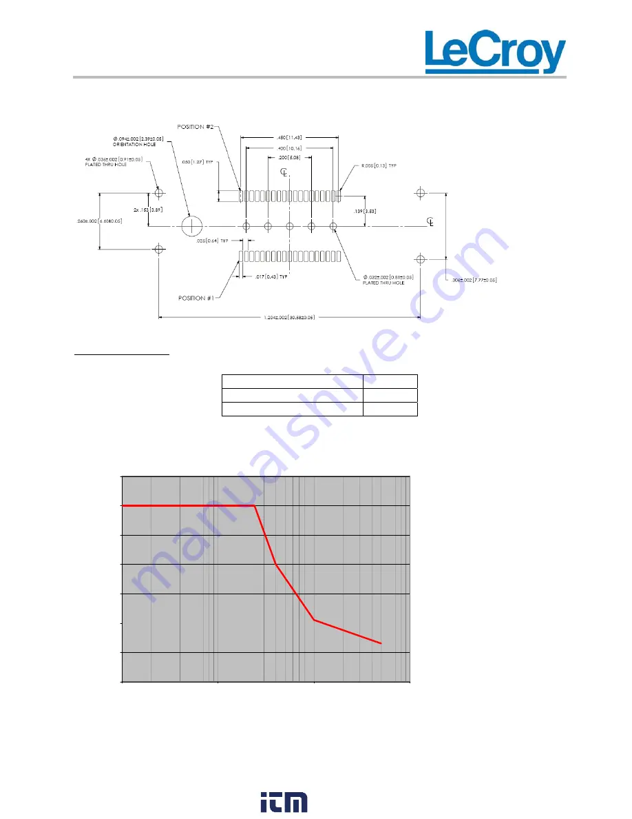
Recommended PCB Layout for Mictor Connector and Shrou
d
SPECIFICATIONS
Input Impedance
100 k
Ω
Attenuation 10:1
Maximum Input Voltage
± 30 V
All specifications are for the MSO-MICTOR cable used with the MS-500 or MS-500-36
Max. V
IN
versus Frequency
Note: Max V
IN
< 30V (DC + Peak AC)
0
5
10
15
20
25
30
35
1 M
10 M
100 M
1000 M
Frequency (Hz)
V
IN
(Vrms)
www.
.com
1.800.561.8187


