EM882S Digital Stepper Drive User Manual
Motion Control Products Ltd. Tel.: (+44) 01202 599922
3.2 P2 - Fault Output Connector
Pin
Details
ALM+
Fault Output Connection: Optional.
(1)
Maximum 24V/80mA output when over-voltage and over-current error protections
activated.
(2)
Sinking or sourcing.
(3)
The resistance between ALM+ and ALM- is low
impedance as default, and will change to high when the drive goes into error protection.
ALM-
3.3 P3 - Motor and Power Connector
PIN
Details
A+
Connect to motor A+ wire
A-
Connect to motor A- wire
B+
Connect to motor B+ wire
B-
Connect to motor B- wire
+VDC
Connect to power supply positive connection. Suggest 24-72VDC power supply voltage
GND
Connect to power supply ground connection.
!
Warning
Warning:
Don’t plug/unplug
P3
connector
to avoid drive damage or injury while powered on.
3.4 P4 - Tuning Port
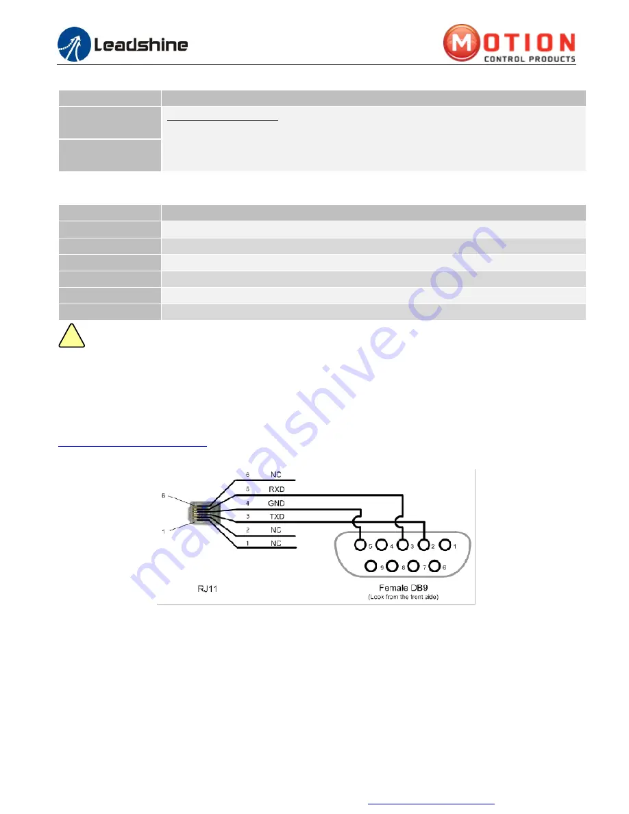
EM882S has a tuning port with RS232 to modify the drive parameters, it
’
s only for tuning, not for equipment control
because neither precision nor stability is sufficient. If you need a field bus drive, contact Motion Control Products Ltd.
For their range of fieldbus servo drives and stepper drives, ideal for performance network control.
The interface definition is as follows:
3.5 Status LED Lights
There are two LED lights for EM882S. The GREEN one is the power indicator which should be always on in normal
circumstance. The RED one is a drive status indication light, which will be OFF while working normally but ON and
flash 1 or 2 times in a 3-second period in the case of enabled over-current or over-voltage protection.
4. Control Signal and Fault Output
4.1 Control Signal Connection
The EM882S can accept differential or single-ended control signals (pulse, direction, and enable) in open-collector or


