Leadshine DM856 Скачать руководство пользователя страница 15


DM856 Digital Stepping Driver Manual V1.0


Tel: +000 0000-00000000                                25                               

Anti-Resonance Introduction 

Step motors are highly resonant, which results in vibration and ringing. The ringing utilizes a large 
fraction  of  the  motor's  available  torque 

  thereby  wasting  performance.  Furthermore,  at  mid-range 

velocities, the resonance can become so severe that the motor looses synchronization and stalls. The 
DM856 driver provides robust anti-resonance control to stop the vibrations and maintain equilibrium. 
This feature requires that the driver be configured with respect to the total inertia in the system. If set 
improperly, the effectiveness of the feature may be diminished.   

The  user  can  invoke  or  disable  the  feature  by  setting 

Amp

  and 

Phase

  values  in 

SystemConfig


window. 

Amp

 and 

Phase

 values all zero is to disable the feature, otherwise is to invoke the feature. It 

should  be  enabled  unless  the  system  configuration  either  does  not  need  it  or  cannot  tolerate  it.  A 
system with loose couplings or viscous loading generally does not need this feature. If a system has 
compliant (springy) coupling and is absent appreciably viscosity, it may not respond well to the active, 
anti-resonant  loop  in  the  drive.  The  anti-resonant  feature  is  not  designed  to  damp  such  a  4

th 

order 

system. If the application of anti-resonance results in degradation or instability, it should be disabled.   
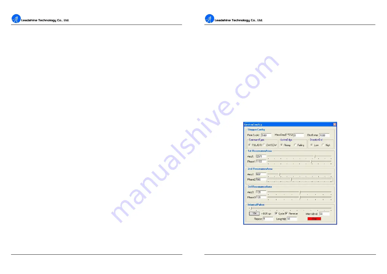
1

st

 ResonanceArea: Parameters for 1

st

 resonance area. 

Usually between 0.6rps and 1.2rps.


Amp1 

is Amplitude adjustment for 1

st

 resonance area.   

Phase1 

is Phase adjustment for 1

st

 resonance area. The user can enter a value directly in the text box 

or move the slider bar back and forth to get an optimum value.   

2

nd

  ResonanceArea:  Parameters  for  2

nd

  resonance  area. 

Usually  between  1.2rps  and  2.4rps. 

Default 

Amp2

 and 

Phase2

 values are zero.


3

rd

 ResonanceArea: Parameters for 3

rd

 resonance area. 

Usually between 2.4rps and 4.8rps. Default 

Amp3

 and 

Phase3

 values are 128.


InternerPulser:

  There  is  an  internal  pulse  generator  designed  for  driver  self-testing  and 

anti-resonance tuning. You can issue a motion by this simple controller. 

Cycle

 check box: The motion will repeat if this box is checked. 

Reverse

 check box: The motor shaft will reverse direction if this box is checked. 

Interval 

edit box: The stop time between each cycle, unit is 

millisecond

Repeat 

edit box: Total


motion cycles.   


DM856 Digital Stepping Driver Manual V1.0


Tel: +000 0000-00000000                                26                           

Length 

edit box: Move distance of each cycle, unit is 

revolution

Start/Stop

 button: The user can Start/Stop a motion test by clicking this button. 

Procedure for Achieving Optimum Performance 

Step  1:

  Start  the  motion  test  by  clicking 

Start/Stop

  button.  Find  an  resonance  speed  by  slightly 

moving the slider bar of internal pulse generator back and forth. See Figure 26. 

Step 2:

 Run the motor at the resonance speed and verify the motor smoothness. You may find a better 

smoothing value by slightly moving the slider bars of 

AMP

(s) and 

Phase

(s) back and forth.   

It is very important to make the 

AMP

(s) and 

Phase

(s) adjustments at the proper test speeds with an 

unloaded motor. Running at an incorrect test speed will not excite the motor at its peak resonance, 
making it more difficult to find proper adjustment values. Optimum 

AMP

(s) and 

Phase

(s) values may 

be a little different between running the tests with an unloaded motor and a load motor.   
Please remember to click 

SavetoDrive

 to download the final parameter settings to the driver when 

finish tuning. See Figure 27. 


Figure 26: Anti-resonance tuning 

Содержание DM856

Страница 1: ...s not assume any liability arising out of the application or use of any product or circuit described herein neither does it convey any license under its patent rights of others Leadshine s general policy does not recommend the use of its products in life support or aircraft applications wherein a failure or malfunction of the product may directly threaten life or injury According to Leadshine s te...

Страница 2: ...n 7 Regulated or Unregulated Power Supply 7 Multiple Drivers 8 Selecting Supply Voltage 8 7 Selecting Microstep Resolution and Driver Output Current 8 Microstep Resolution Selection 8 Current Settings 9 Contents II Dynamic current setting 10 Standstill current setting 10 8 Wiring Notes 10 9 Typical Connection 11 10 Sequence Chart of Control Signals 11 11 Protection Functions 12 Over current Protec...

Страница 3: ... microstep output for smooth system performance l Microstep resolutions programmable from full step to 102 400 steps rev l Supply voltage up to 80 VDC l Output current programmable from 0 5A to 5 6A l Pulse input frequency up to 200 KHz l TTL compatible and optically isolated input l Automatic idle current reduction l Suitable for 2 phase and 4 phase motors l Support PUL DIR and CW CCW modes l Ove...

Страница 4: ...response DIR signal should be ahead of PUL signal by 5μs at least 4 5V when DIR HIGH 0 0 5V when DIR LOW Please note that rotation direction is also related to motor driver wiring match Exchanging the connection of two wires for a coil to the driver will reverse motion direction ENA ENA Enable signal This signal is used for enabling disabling the driver High level NPN control signal PNP and Differ...

Страница 5: ... at higher speeds This configuration is also referred to as half chopper In DM856 Digital Stepping Driver Manual V1 0 Tel 000 0000 00000000 6 setting the driver output current multiply the specified per phase or unipolar current rating by 1 4 to determine the peak output current Figure 5 6 lead motor half coil higher speed connections Full Coil Configurations The full coil configuration on a six l...

Страница 6: ...he reason is that the driver draws current from the power supply capacitor of the unregulated supply only during the ON duration of the PWM cycle but not during the OFF duration Therefore the average current withdrawn from power supply is considerably less than motor current For example two 3A motors can be well supplied by one power supply of 4A rating DM856 Digital Stepping Driver Manual V1 0 Te...

Страница 7: ... RMS Current SW1 SW2 SW3 Default Software configured 0 5 to 5 6A OFF OFF OFF 2 1A 1 5A ON OFF OFF 2 7A 1 9A OFF ON OFF 3 2A 2 3A ON ON OFF 3 8A 2 7A OFF OFF ON 4 3A 3 1A ON OFF ON 4 9A 3 5A OFF ON ON 5 6A 4 0A ON ON ON Notes Due to motor inductance the actual current in the coil may be smaller than the dynamic current setting particularly under high speed condition Standstill current setting SW4 i...

Страница 8: ...ate what protection has been activated The periodic time of RED is 3 s seconds and how many times the RED turns on indicates what protection has been activated Because only one protection can be displayed by RED LED so the driver will decide what error to display according to their priorities See the following Protection Indications table for displaying priorities Over current Protection Over curr...

Страница 9: ...assistance Many of the problems that affect motion control systems can be traced to electrical noise controller software errors or mistake in wiring DM856 Digital Stepping Driver Manual V1 0 Tel 000 0000 00000000 14 Problem Symptoms and Possible Causes Symptoms Possible Problems No power Microstep resolution setting is wrong DIP switch current setting is wrong Fault condition exists Motor is not r...

Страница 10: ... have 1 serial port at least for communicating with the driver Double click ProTuner_All_Setup_V1 0 exe to begin installing the ProTuner See Figure 11 Click Next to enter the License Agreement window See Figure 12 Figure 11 Begin to install the ProTuner Note ProTuner_All_Setup_V1 0 exe can be used for all Leadshine digital drives User can get it from either Leadshine CD or website Please get the l...

Страница 11: ...ortcut Folder in Figure 15 and continue to install the ProTuner by following Figure 16 and Figure 17 An Installation Successful window will appear if the ProTuner is installed successfully See Figure 18 DM856 Digital Stepping Driver Manual V1 0 Tel 000 0000 00000000 18 Figure 16 Installation information summarization Figure 17 Installing the ProTuner ...

Страница 12: ...ely turns on flickers then check power supply the motor motor wirings DM856 DM856 Digital Stepping Driver Manual V1 0 Tel 000 0000 00000000 20 and try again Open the tuning software ProTuner and check driver status by clicking Err_check If it s Phase Error check the motor motor wirings and try again If the RED LED is off and the motor is normal then you can start to tune the servo with ProTuner Ho...

Страница 13: ...otors Start Restart a Step Response test to get an optimum response Kp Proportional Gain Proportional Gain determines the response of the driver to current setting command Low Proportional Gain provides a stable system doesn t oscillate has low stiffness and large current error causing poor performances in tracking current setting command in each step like Figure 23 Too large Proportional Gain val...

Страница 14: ...ion and Driver Output Current MicroStep Microstep Resolution The value is driver s microstep resolution setting and can be set from 1 to 512 The user can set the microstep with ProTuner or DIP switches See more information about setting output current of the driver in section 7 Selecting Microstep Resolution and Driver Output Current DM856 Digital Stepping Driver Manual V1 0 Tel 000 0000 00000000 ...

Страница 15: ...to get an optimum value 2nd ResonanceArea Parameters for 2nd resonance area Usually between 1 2rps and 2 4rps Default Amp2 and Phase2 values are zero 3rd ResonanceArea Parameters for 3rd resonance area Usually between 2 4rps and 4 8rps Default Amp3 and Phase3 values are 128 InternerPulser There is an internal pulse generator designed for driver self testing and anti resonance tuning You can issue ...

Страница 16: ...r Manual V1 0 Tel 000 0000 00000000 28 OverVoltage Over voltage Protection When power supply voltage exceeds 91 1 VDC protection will be activated PhaseErr Phase Error Protection Motor power lines wrong not connected will activate this protection ErrCounter Displays current error s and current error history Erase Current Err Erase Current Err button The user can clear current error s by clicking t...

Отзывы: