Leadshine CS-D808 Скачать руководство пользователя страница 6

                                                                                  CS-D808 Closed Loop Stepper Drive User Manual                                                             


Page | 3   


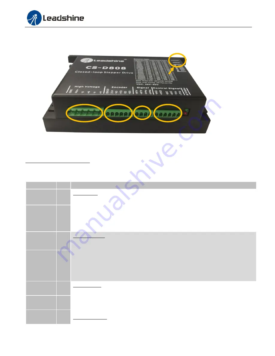
3. Connections and LED Indication 

A CS-D808 closed loop stepper drive has 5 connection blocks from P1 to P5 (see figure 2). 


Figure 2: CS-D808 connectors 

3.1 Connector P1 & P2– Control Input and Output Connections 

3.1.1 Pin Assignments of P1 & P2 

The P1 & P2 connector in Figure 2 is for control signal and fault output connections. Refer to the following table for 

details. 

Pin Name 

I/O 

Details 

PUL+ 

Pulse signal: 

(1)

. In single pulse (pulse & direction) control  mode, this input represents pulse 

signal. A pulse signal is active at the rising or falling voltage edge (set by PC software). 

(2).

 In 

double-pulse  (CW/CCW)  control  mode  (set  by  PC  software),  this  signal  input  represents 

clockwise  (CW)  pulse,  and  is  active  at  both  high  voltage  level  and  low  voltage  level. 

(3).


4.5-24V  for  voltage  HIGH,  0-0.5V  for  voltage  LOW  (same  for  DIR  and  ENA  signals). 

(4).


Pulse width should be set to 2.5μs or longer. 

PUL- 

DIR+ 

Direction signal: 

(1).

 In single pulse (step & direction) control mode, this signal’s low and high 

voltage  levels  represent  the  two  directions  of  motor  rotation  (e.g.  clockwise  and 

counterclockwise). 

(2).

  In  double-pulse  (CW  &  CCW)  control  mode,  this  signal  represents 

counterclockwise  (CCW)  rotation.  It  is  active  at  both  voltage  high  level  and  low  level. 

(3). 

Minimal DIR signal setup time should be at least 5μs. 

(4).

 Rotation direction is related to your 

motor/drive  wiring.  You  can  reverse  the  default  rotation  direction  by  toggling  the  SW5  DIP 

switch. 

DIR- 

ENA+ 

Enable  signal:  This  signal  is  used  for  enabling/disabling  the  drive.  High  voltage  level  of 

4.5-24V  (NPN  control  signal)  for  enabling  the  drive  and  low  voltage  level  of  0-0.5VDC  for 

disabling the drive. PNP and Differential control signals are on the contrary, namely Low level 

for enabling.    By default this signal is left 

UNCONNECTED & ENABLED

ENA- 

Pend+ 

In-position Signal: OC output signal, active when the difference between the actual position and 

P1 

P2 

P3 

P4 

P5 

Содержание CS-D808

Страница 1: ...Loop Stepper Drive Revision 1 0 2016 Leadshine Technology Co Ltd Address Floor 11 Block A3 Nanshan iPark Xueyuan Avenue 1001 Shenzhen Guangdong 518055 China Tel 86 755 26409254 Fax 86 755 26402718 We...

Страница 2: ...therwise without approval from Leadshine While every precaution has been taken in the preparation of the book Leadshine assumes no responsibility for errors or omissions Neither is any liability assum...

Страница 3: ...4 3 3 Connector P4 Motor and Power Supply Connection 5 3 4 Connector P5 RS232 Connection 5 3 5 LED Light Indication 5 4 Motor Selection 5 5 Power Supply Selection 5 5 1 Regulated or Unregulated Power...

Страница 4: ...reduced heating lower noise low vibration 1 1 Features No loss of step No torque reservation No hunting or overshooting No tuning for easy setup Low noise and vibration smooth motion 30 80VDC supply v...

Страница 5: ...ation 10 50Hz 0 15mm Storage Temperature 20 C 65 C 4 F 149 F Weight Approx 570 g 20 2 Oz 2 3 Mechanical Specifications unit mm 1inch 25 4mm Figure 1 Mechanical specifications 2 4 Heat Dissipation CS D...

Страница 6: ...gnals 4 Pulse width should be set to 2 5 s or longer PUL I DIR I Direction signal 1 In single pulse step direction control mode this signal s low and high voltage levels represent the two directions o...

Страница 7: ...ts open collector and PNP output A CS D808 has 3 optically isolated control inputs PUL DIR and ENA Refer to the following two figures for connections of open collector and PNP signals Controller Contr...

Страница 8: ...tuning purpose only not for RS232 command controls 3 5 LED Light Indication There are two LED lights for CS D808 one red and one green The GREEN one is the power indicator which will be always on gen...

Страница 9: ...e drive draws current from the power supply capacitor of the unregulated supply only during the ON duration of the PWM cycle but not during the OFF duration Therefore the average current withdrawn fro...

Страница 10: ...12800 off on off on 25600 on off off on 51200 off off off on 1000 on on on off 2000 off on on off 4000 on off on off 5000 off off on off 8000 on on off off 10000 off on off off 20000 on off off off 40...

Страница 11: ...ension Cable Power Cable 3 B B Yellow Green Blue CS D808 Fault 5V ALM 1 2 ALM In Positiion Pend 1 2 Pend Figure 6 Typical connection 8 Sequence Chart of Control Signals In order to avoid some fault op...

Страница 12: ...u want to do fine tuning or custom configurations such as micro step current percentage change you can use Leadshine s free ProTuner software to make the changes Download ProTuner at http www leadshin...

Страница 13: ...el is reverse Toggling the SW5 DIP switch The drive in fault Red light flashes once in a 5 second period The motor coil may short circuit or exiting the wrong wiring Red light flashes twice in a 5 sec...

Страница 14: ...ation or misuse or operation beyond the electrical specifications of the product and or operation beyond environmental specifications for the product Obtaining Warranty Service To obtain warranty serv...

Страница 15: ...h 24VDC brake CS M23480 8 0 1132 127 3 03 0 551 inch 14 mm shaft CS M23480 S 8 0 1132 127 3 82 0 50 inch 12 7 mm shaft CS M23480B 8 0 1132 173 3 82 0 551 inch 14 mm shaft with 24VDC brake CS M23485 8...

Страница 16: ...or stepper and servo controls Model Output Voltage VDC Series Model Continuous Current A Max Current A Input Voltage VAC RPS488V20 48 RPS 8 3 24 9 85 132 176 264 RPS4810V20 48 10 5 31 5 85 132 176 264...

Отзывы: