


D
D
B
B
8
8
1
1
0
0
A
A
D
D
i
i
g
g
i
i
t
t
a
a
l
l
D
D
C
C
S
S
e
e
r
r
v
v
o
o
D
D
r
r
i
i
v
v
e
e
r
r
M
M
a
a
n
n
u
u
a
a
l
l
V
V
1
1
.
.
0
0
Tel: (86)755-26434369
21
Web site: www.leadshine.com
The other condition is the POSITION FOLLOWING ERROR exceeds
±
128 counts
causing servo-lock. This condition may have several causes:
1) The servo system is UNSTABLE or severely UNDER DAMPED, causing
POSITION FOLLOWING ERROR limit occurs.
2) Excessive motor load due to acceleration or workload, the POSITION
FOLLOWING ERROR exceeds
±
128 counts causing servo-lock.
3) The speed command in excess of what the motor can deliver, causing
POSITION FOLLOWING ERROR occurs.
4) The current Limit is set too low, causing the motor can
’
t output enough torque
to follow the commanding and POSITION FOLLOWING ERROR occurs.
5) The power supply current is insufficient for the application, causing the motor
can
’
t output enough torque to follow the commanding and POSITION
FOLLOWING ERROR occurs.
6) The motor is wired backwards, or is broken or disconnected.
7) Encoder failure or is wired backwards.
Changing Default Motor Direction
The DB810A will turn the motor in the CW direction when the direction input is
“
high
”
(logical
“
1
”
). If instead CCW is preferred, then:
1) Reverse the
“
motor +
”
and
“
motor -
”
leads.
2) Reverse the encoder
“
Channel A
”
and
“
Channel B
”
leads.
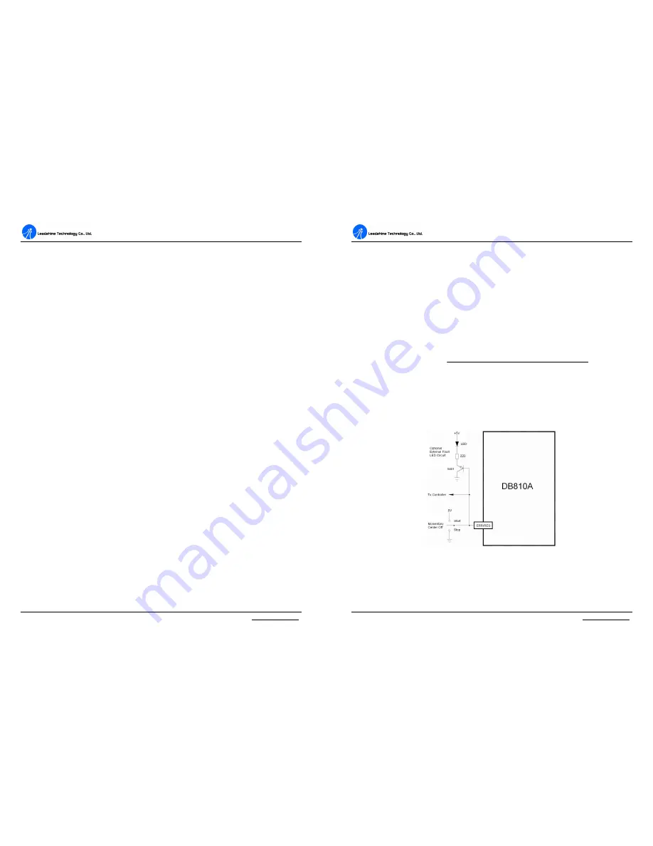
ERR/RES Port
This port functions as an error output and as a servo start/restart input. When first
testing the DB810A or it is not necessary to read the state of the error output,
ERR/RES port can be connected to E +5V port.
When the DB810A is functioning normally, the voltage on this terminal is +5VDC.
The voltage on this terminal will goes to 0VDC when the Alarm LED is lit. This
output can be used to signal your controller that an error has occurred.
D
D
B
B
8
8
1
1
0
0
A
A
D
D
i
i
g
g
i
i
t
t
a
a
l
l
D
D
C
C
S
S
e
e
r
r
v
v
o
o
D
D
r
r
i
i
v
v
e
e
r
r
M
M
a
a
n
n
u
u
a
a
l
l
V
V
1
1
.
.
0
0
Tel: (86)755-26434369
22
Web site: www.leadshine.com
Figure 19 shows an external switch to clear an ERROR condition and
START/RESET the DB810A, while still can read the state of the drive. It also
includes an optional Alarm LED circuit if a remote state indication is desired.
Maximum Pulse Input Frequency
The highest frequency at which the drive can interpret encoder feedback. To convert
this frequency to RPM, use the following formula:
4
)
(
60
)
(
(max)
´
´
=
Count
Line
Encoder
Frequence
Input
Pulse
Max
RPM
Figure 19: Alarm indication and start/stop circuit of the DB810A