background image

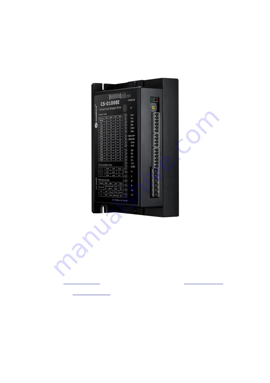
CS-D1008E

Closed Loop Stepper Drive

User Manual

Revision 1.0

©2020 Leadshine Technology Co., Ltd.

Address:

15-20/F, Block B, Nanshan I Valley, No.3185, Shahe West Road, Nanshan District,

Shenzhen, Guangdong, 518055, China

Tel:

(86)755-26409254

Fax:

(86)755-26402718

Web:

www.leadshine.com

Sales:

[email protected]

Support:

[email protected]

Содержание CS-D1008E

Страница 1: ... 2020 Leadshine Technology Co Ltd Address 15 20 F Block B Nanshan I Valley No 3185 Shahe West Road Nanshan District Shenzhen Guangdong 518055 China Tel 86 755 26409254 Fax 86 755 26402718 Web www leadshine com Sales sales leadshine com Support tech leadshine com ...

Страница 2: ... otherwise without approval from Leadshine While every precaution has been taken in the preparation of the book Leadshine assumes no responsibility for errors or omissions Neither is any liability assumed for damages resulting from the use of the information contained herein This document is proprietary information of Leadshine that is furnished for customer use ONLY Information in this document i...

Страница 3: ...1 Pin Assignments of P1 4 3 1 2 Connection of Control Signals 5 3 2 Connector P2 Outputs Connector 5 3 2 1 Pin Assignments of P2 5 3 2 2 Connection of In position and Alarm 6 3 2 3 Connection of Brake Signal 6 3 3 Connector P3 Encoder Connector 7 3 4 Connector P4 Motor Power Connection 7 3 5 Connector P5 Tuning Port 8 3 6 LED Light Indication 8 4 Motor Selection 8 5 Power Supply Selection 8 5 1 Re...

Страница 4: ...3 S3 Selector Switch Configurations 11 7 Typical Connection 11 8 Sequence Chart of Control Signals 12 9 Fault Protections 12 10 Software Configuration 13 11 Accessories 13 12 Troubleshooting 14 13 Warranty 16 Appendix A Leadshine CS D1008E Compatible Stepper Motors 17 Appendix B Leadshine CS D1008E Compatible Power Supplies 18 Appendix C Powering a Third Party Motor with CS D1008E 18 ...

Страница 5: ... torque reservation No hunting or overshooting No tuning for easy setup Enhance performance especially at low speed application 60RPM Auto tuning to match wide range NEMA 23 24 and 34 closed loop stepper motors Soft start with no jump when powered on 18 80VAC or 24 110VDC supply voltage max 8 0A output current Max 500 KHz input frequency 15 micro step settings of 800 51 200 via DIP switches or 200...

Страница 6: ...ncy 5V 50 dutycycle 0 500 kHz Pulse input frequency 24V 50 dutycycle 0 200 KHz Minimal pulse width 1μS 5V or 2 5μS 24V μS Minimal direction setup 5 0 μS Isolation resistance 100 MΩ 2 2 Environment Cooling Natural Cooling or Forced Cooling Operating Environment Environment Avoid dust oil fog and corrosive gases Humidity 40 RH 90 RH Operating Temperature 0 C 40 C 32 F 104 F Vibration 10 50Hz 0 15mm ...

Страница 7: ...fications 2 4 Heat Dissipation Temperature of the drive during working should be no more than 65 149 F It is recommended to mount the drive vertically to maximize heat dissipation Mount a cooling fan nearby if necessary If multiple CS D1008E drives are installed it is suggested to keep a minimal 30mm 1 2 inches between two of them ...

Страница 8: ...0KHz for 24V 3 The width of PUL signal is at least 1 0μs or 2 5μs duty cycle is recommended 50 4 Single pulse step direction or double pulse CW CCW is set by DIP Switch SW7 5 DIR signal requires advance PUL signal minimum 5 μs in single pulse mode 6 The factory setting of control signal voltage is 24V must need to set S3 figure 2 if it is 5V PUL CW I DIR CCW I DIR CCW I ENA I Enable Signals Option...

Страница 9: ...al is no connected as default 2 Control signal amplitude is 24 V as default If it is 12 V please set the S3 Figure 2 selector switch to 5 V first then connect 1KΩ resistor If it is 5V please set the S3 to 5V 3 2 Connector P2 Outputs Connector 3 2 1 Pin Assignments of P2 PIN I O Details BRK INP O Select Brake or In position function via DIP Switch SW8 Brake Max 30VDC 100mA connect with brake coil r...

Страница 10: ...like a PLC For example in a multi axis system like a CNC machine when one of the axes fails such a fault output signal can be feedback to the motion controller for a followed action e g auto machine shutdown auto error clearing etc Connection Refer to the following figure Figure 4 ALM Signals Connection 3 2 3 Connection of Brake Signal This signal can be used for automatic brake control while syst...

Страница 11: ... connection 3 4 Connector P4 Motor Power Connection The P4 connector in Figure 2 is for motor and power connection Refer to the following table for details Pin Name Details A Stepper motor A connection Connect motor A wire to this pin A Stepper motor A connection Connect motor A wire to this pin B Stepper motor B connection Connect motor B wire to this pin B Stepper motor B connection Connect moto...

Страница 12: ...remental encoders recommend 1000 line Leadshine offers many high performance stepper motors compatible with the CS D1008E which you can find in the Appendix A of this document The CS D1008E can also power similar stepper motors with incremental encoders from third party suppliers Notes Contact Leadshine for stepper motor with 2000 line 2500 line 5000 line encoders 5 Power Supply Selection The CS D...

Страница 13: ... power line voltage fluctuation and back EMF voltage generated during motor deceleration needs also to be taken into account Ideally it is suggested to use a power supply with the output of 30 90VDC or 20 70VAC leaving room for power line voltage fluctuation and back EMF If using an AC transformer be sure to use a transformer with isolation Otherwise there is a risk of electrocution 6 DIP Switch C...

Страница 14: ...tandstill current as shown below SW1 SW2 SW3 SW4 SW5 SW6 SW7 SW8 Figure 6 DIP switches 6 2 1 Micro Step SW1 SW4 Each CS D1008E has 15 microstep settings which can be configured through DIP switches SW1 SW2 SW3 and SW4 See the following table for detail Micro step Pulses Rev for 1 8 motor SW1 SW2 SW3 SW4 8 default 1600 on on on on 4 800 off on on on 8 factory 1600 on off on on 16 3200 off off on on...

Страница 15: ... the encoder is damaged or judging whether the value of the position loop gain is wrong 6 3 S3 Selector Switch Configurations The 1 bit selector is located on the top S3 in figure 2 used to configure the voltage of control signals For safety reasons the factory setting is 24 V When connecting to a PLC it is not necessary to connect a 2K resistor which is simpler and more convenient to use When the...

Страница 16: ...hs are based on a 50 duty cycle If it is greater or less than 50 the width time is required to be wider 9 Fault Protections To improve reliability the drive incorporates some built in protection features Blink time s Sequence wave of red LED Description Trouble shooting 1 0 2S 5S Over current Turn off the power immediately a Check wiring is short circuited or not b Check motor is short circuited o...

Страница 17: ...bove problems 10 Software Configuration The CS D1008E is designed for simple setup and implementation For most applications no software configuration or tuning is needed especially when driving Leadshine stepper motors with encoders see Appendix A If you want to do fine tuning or custom configurations such as micro step current percentage change you can use Leadshine s free MotionStudio software t...

Страница 18: ...icrostep resolution setting is wrong Setting appropriate microstep Fault condition exists Check wiring and restart power The drive is disabled Drive restore factory setting and keep ENA ENA input signals unconnected Wrong motor rotation direction The Direction signal level is reverse Toggling the SW5 DIP switch The drive in fault Red light flashes once in a 5 second period The motor coil may short...

Страница 19: ...eleration Power supply voltage too low Choose another power supply with large voltage output Excessive motor drive heating Inadequate heat sinking cooling Refer to chapter 2 4 Motor peak current setting is too high Reduce the current value refer to motor datasheet Motor vibration when power on Position loop Kp is too high Reduce the position loop Kp value Motor only one direction DIR inputs is bur...

Страница 20: ...ication or misuse or operation beyond the electrical specifications of the product and or operation beyond environmental specifications for the product Obtaining Warranty Service To obtain warranty service please contact your seller to obtain a returned material authorization number RMA before returning product for service Shipping Failed Products If your product fail during the warranty period pl...

Страница 21: ...0 50 inch 12 7 mm shaft CS M23445B 4 5 637 144 5 67 24VDC brake integrated CS M23445WP 4 5 637 115 4 53 IP65 rated CS M23480 8 0 1132 127 4 96 CS M23480 S 8 0 1132 127 4 96 0 50 inch 12 7 mm shaft CS M23485 8 5 1202 147 5 79 CS M23485 S 8 5 1202 147 5 79 0 50 inch 12 7 mm shaft CS M23485B 8 5 1202 182 7 17 24VDC brake integrated CS M23485WP 8 5 1202 154 6 06 IP65 rated CS M234120 12 0 1698 158 6 2...

Страница 22: ...shine carry s many other custom models and there may be one there which can satisfy your application need already In the case of powering a third party closed loop stepper motor pay special attention as described below Your stepper motor must be a 2 phase stepper motor Your stepper motor must be mounted with a quadrature rotary encoder with the resolution of 500 5 000 line 2 000 20 000 CPR When th...

Отзывы: