background image

LV 5333 

MULTI SDI MONITOR 

LV 5333 OP70 

BATTERY ADAPTER V MOUNT 

LV 5333 OP71 

BATTERY ADAPTER QR GOLD MOUNT 

INSTRUCTION MANUAL 

99 Washington Street 
Melrose, MA 02176 

Phone

 781-665-

1400

Toll Free 1-800-517-8431

Visit us at www.T

estEquipmentDepot.com

Содержание LV 5333

Страница 1: ...OR LV 5333 OP70 BATTERY ADAPTER V MOUNT LV 5333 OP71 BATTERY ADAPTER QR GOLD MOUNT INSTRUCTION MANUAL 99 Washington Street Melrose MA 02176 Phone 781 665 1400 Toll Free 1 800 517 8431 Visit us at www...

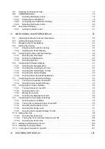
Страница 2: ...rmat Settings 7 2 3 3 Embedded Audio Playback Format 7 2 3 4 I O Connectors 7 2 3 5 Control Connectors 8 2 3 6 LCD 8 2 3 7 Display Format 9 2 3 8 Video Signal Waveform Display 9 2 3 9 Vectorscope Disp...

Страница 3: ...34 5 3 3 Displaying the Time 35 5 3 4 Displaying the Color System 35 5 3 5 Displaying the Time Code 35 5 3 6 Setting the Backlight 35 5 3 7 Selecting the Auto Shutoff Time 35 5 3 8 Selecting the Colo...

Страница 4: ...ff 58 8 4 2 Setting the Line Selection Range 58 8 5 Other Settings 59 8 5 1 Displaying Closed Captions 59 8 5 2 Selecting the Closed Caption Format 60 8 5 3 Displaying the Histogram 61 8 5 4 Selecting...

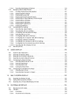
Страница 5: ...at 89 11 6 3 Selecting the Field Display Format 89 11 6 4 Selecting the Field to Display 90 11 6 5 Selecting the Horizontal Magnification 90 11 7 Configuring the Line Selection Settings 92 11 7 1 Turn...

Страница 6: ...Display Unit 112 12 9 Phase Difference Display 113 12 9 1 Phase Difference Screen Description 113 12 9 2 Selecting the Memory Number 116 12 9 3 Saving the Phase Difference 116 12 9 4 Deleting a Phase...

Страница 7: ...rror Settings 150 13 6 8 Configuring the Luminance Level Error Settings 152 13 6 9 Configuring the Chrominance Level Error Settings 154 13 6 10 Selecting the Error Display Format 154 13 7 Resetting Er...

Страница 8: ...rise MIB 185 16 4 5 Specific Trap 204 16 4 6 Variable Binding List 205 17 MENU TREE 17 206 17 1 Picture Menu 17 206 17 2 CINELITE Menu 17 207 17 3 CINEZONE Menu 17 208 17 4 WFM Menu 17 208 17 5 VECTOR...

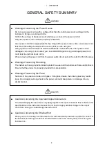
Страница 9: ...o understand If you have any questions about the contents of this manual please contact your localLEADER agent Symbols and Terms The following symbols and terms are used in this instruction manual and...

Страница 10: ...that the instrument has condensation within it waitfor approximately 30 minutes before turning on the power Operating Humidity Range Use this instrument in an environment whose relative humidity is 8...

Страница 11: ...on the cord Pull from the plug Warnings Concerning Grounding The instrument has a ground terminal to protect the user and the instrument from electricshock Ensure that the product is properly grounde...

Страница 12: ...ft cloth with mild detergent and wipe gently While cleaning make surethat foreign materials such as water and detergent do not enter the instrument If liquid or ametal object enters into the instrumen...

Страница 13: ...tage applied by the user 2 Repair of an instrument that has been improperly repaired adjusted or modified by personnel other than a factory trained LEADER representative 3 Repair of malfunctions or da...

Страница 14: ...gments The company and product names in this document are trademarks orregistered trademarks of their respective holders 1 4 Terminology Used in This Manual 1 Screen Display The state that the LV 5333...

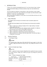
Страница 15: ...e displays is also available CINELITE II and CINELITE Advanced The LV 5333 is standard equipped with CINELITE II CINELITE and CINEZONE and CINELITE Advanced which are video signal luminance informatio...

Страница 16: ...he panel transfer files andmonitor errors Tripod and VESA Mounting There are 75 mm VESA compliant mounting holes on the back of the LV 5333 so it canbe mounted on a stand In addition the tripod adapte...

Страница 17: ...80 60 59 94 50 I SMPTE ST 274 30 29 97 25 24 23 98 P 30 29 97 25 24 23 98 PsF Table 2 4 3G A image format and compliantstandards Color System Quantization Image Frame Field Frequency Scanning Complian...

Страница 18: ...1920 1080 60 59 94 50 I 30 29 97 25 24 23 98 P 30 29 97 25 24 23 98 PsF RGB 4 4 4 10bit 1920 1080 60 59 94 50 I 30 29 97 25 24 23 98 P 30 29 97 25 24 23 98 PsF 12bit 1920 1080 60 59 94 50 I 30 29 97 2...

Страница 19: ...o clock Synchronization All audio signals must be synchronized to the video clock Phases All phases must be in sync Channel Separation Select 2 groups of 8 channels each 2 3 4 I O Connectors SDI Input...

Страница 20: ...turned on is indefinite External sync mode does not work for 30 29 97 25 24 23 98 P for 3G A 1280 720 2 3 5 Control Connectors USB Port Function Saves screen captures preset data event log data and d...

Страница 21: ...nal color system at the top of the screen Date Display Displays the time based on the internal clock at the top of the screen Time and Time Code Display Displays the time based on the internal clock o...

Страница 22: ...2 REF and DELTA Vertical Cursors 2 REF and DELTA Amplitude Measurement mV R DEC HEX Time Measurement sec Frequency Display Computes and displays the frequency with the length of one period set to the...

Страница 23: ...nly removes transient errors can be turned on and off Displays the selected line 2 3 11 Phase Difference Display Display Display Range Displays the phase difference between an SDI signal and the exter...

Страница 24: ...an object with an 18 reflectance f Stop Gamma Correction Fundamental Gamma 0 45 ITU R BT 709 User Correction Table 3 types Display Displays the luminance level or RGB level as a percentage Gradation...

Страница 25: ...play Numeric Display Displayed Channels 8ch Meters 60 dB peak level 90 dB peak level average response Reference Level 20dB 18dB 12dB 9dB Scale dBFS with the reference level set to 0 dB Peak Hold Time...

Страница 26: ...105 m 105 m HD 5 m 5 to 130 m 130 m SD 50 m 50 to 300 m 300 m Resolution 5m Accuracy 20m Error Count Up to 100000 errors counts only the specified errors Count Period Once regardless of the number of...

Страница 27: ...ry 2 3 17 Screen Capture Function Display Media Data Output Data Input Captures the screen Displays only the captured image or overlays the captured image over the input signal Internal memory RAM and...

Страница 28: ...tings 2 3 21 Rear Panel Stand 75 mm VESA compliant mounting Battery adapter 1 A separately sold option can be used to attach a V mount or QR gold mount battery 1 If a battery adapter is attached the 7...

Страница 29: ...gnal Input 4 CAPTURE Captures the screen See chapter 6 CAPTUREFEATURE 5 SYSTEM Configures the settings See chapter 5 SYSTEM SETTINGS 6 MEMORY Press this key to register or delete a single preset setti...

Страница 30: ...19 AUDIO Display audio levels See chapter 14 AUDIO DISPLAY 20 Headphone Jack This is a mini plug headphone jack It outputs the audio embedded in the SDI signal See section 14 6 Headphone Settings 21 U...

Страница 31: ...rinted on this label 4 REMOTE 15 pin D sub remote controlconnector This can be used to execute actions such as recalling presetsettings See section 16 1 Remote Control Feature 5 DC INPUT DC inlet See...

Страница 32: ...3 PANEL DESCRIPTION 20 No Name Description 10 Fan Cooling fan for the instrument...

Страница 33: ...N 21 3 3 Bottom Panel Figure 3 3 Bottom panel Table 3 3 Bottom panel description No Name Description 1 Tripod adapter Used to attach a tripod The adapter can be moved to the top panel See section 4 1...

Страница 34: ...r can be moved to the top panel To do so you will need a hex key 2 mm Please use your own hex key 4 2 Installing a VESA Stand You can attach an off the shelf VESA compliant 75 mm 75 mm stand to the VE...

Страница 35: ...Settingthe License Each LV 5333 requires a unique license key You cannot use the same key for multiple instruments 4 4 Turning the Instrument On and Off Applying DC Power The DC input and its pinout a...

Страница 36: ...turn the power off or remove the USB memory device while it is being accessed Note that some USB memory devices cannot be recognized by the LV 5333 If the icon does not appear when a USB memory devic...

Страница 37: ...waveforms Apply a tri level sync signal or an NTSC PAL black burst signal to the connectors and then press REFE INT EXT The input format is detected automatically As shown in the figure below the exte...

Страница 38: ...cally detected Input Signal Format 525i 59 94 625i 50 1080i 60 1080i 59 94 1080i 50 1080PsF 30 1080PsF 29 97 1080PsF 25 1080PsF 24 1080PsF 23 98 1080p 30 1080p 29 97 1080p 25 1080p 24 1080p 23 98 720p...

Страница 39: ...TSC 59 94Hz PAL 50Hz 1080i 60 1080i 59 94 1080i 50 1080PsF 30 1080PsF 29 97 1080PsF 25 1080PsF 24 1080PsF 23 98 1080p 30 1080p 29 97 1080p 25 1080p 24 1080p 23 98 720p 60 720p 59 94 720p 50 1 If the i...

Страница 40: ...re above for MODE press repeatedly to select the setting you want The setting changes each time you press F 1 After you stop pressing F 1 the setting is confirmed and the pop up menu disappears Note t...

Страница 41: ...eference 5 3 1 Format Display 5 1 Setting the Input Format 2 Color System The input signal color system and quantization accuracy are displayed You can also choose to hide this information If no signa...

Страница 42: ...a USB memory device is connected See section 4 5 Connecting a USB Memory Device 9 Tally This appears in green when pin 13 of the remote connector is connected to ground It is not displayed on some scr...

Страница 43: ...etect the input format automatically or to set it manually follow the procedure below Procedure 5 1 2 Selecting the Display Format Even if you set following formats MODE to AUTO the LV 5333 will be un...

Страница 44: ...IMAGE FORMAT F 4 COLOR FORMAT F 5 PIXEL DEPTH F 6 FIELD RATE F 6 FRAME RATE HD 3G B_S1 3G B_S2 1080i YCbCr422 10bit 60 59 94 50 1080p YCbCr422 10bit 30 29 97 25 24 23 98 1080sF YCbCr422 10bit 30 29 9...

Страница 45: ...12bit 30 29 97 25 24 23 98 RGB444 10bit 12bit 30 29 97 25 24 23 98 HD1080sF YCbCr422 12bit 30 29 97 25 24 23 98 YCbCr444 10bit 12bit 30 29 97 25 24 23 98 RGB444 10bit 12bit 30 29 97 25 24 23 98 2K108...

Страница 46: ...the screen and onthe status screen Procedure 5 3 2 Displaying the Date To select the display format of the date shown at the top of the screen follow the procedure below The date is also displayed on...

Страница 47: ...r off the color system display e g YCbCr422 10b at the top of thescreen follow the procedure below If FORMAT is set to FREQ ON cannot be selected Procedure 5 3 5 Displaying the Time Code When TIME is...

Страница 48: ...when an IDX battery is in use Do not select this when an OP71 is installed ANTON The accurate battery level is displayed when an Anton Bauer battery is in use Do not select this when an OP70 is instal...

Страница 49: ...Settings BIT P1 through P8 are assigned to preset numbers 1 through 8 and you can load one of the eight presets BINARY P5 is set to the MSB and P1 is set to the LSB You can load one of any of the 30...

Страница 50: ...ually To set IP_ADDRESS SUBNET_MASK and GATEWAY follow the procedure below Use F 5 or F 6 to move the cursor and function dial F D to change the value Procedure 5 4 3 Configuring SNMP To select the SN...

Страница 51: ...r license key ready and follow the procedure below to install theoption 1 Enter the license key Turn the function dial F D to select the number and press to enter it You can also enter the number by p...

Страница 52: ...press SHORT CUT Use this setting in adark environment when the keys are difficult to see The key LEDs turn off when you perform the next operation CAP USB A screen capture will be taken when you pres...

Страница 53: ...at are initialized Item Standard initialization Factory default initialization Ethernet settings No Yes License settings No No Date and time No No Presets 1 No Yes User defined correction table for CI...

Страница 54: ...rform one of the following operations after taking a screen capture the captured data will be deleted Change the measurement screen Press the SYSTEM MEMORY or RECALL key Turn off the power Figure 6 1...

Страница 55: ...ory device to the LV 5333 2 Press TYPE SELECT to select the file format BMP BSX Files are saved to a USB memory device in BMP and BSX formats Youcan view the saved files on a PC or redisplay it on the...

Страница 56: ...at has been saved in BSX format on a different model cannot be displayed on the LV5333 1 Connect a USB memory device to the LV 5333 2 Press CAPTURE The CAPTURE menu appears 3 Press USB MEMORY The file...

Страница 57: ...on the PC 1 Connect a USB memory device to the LV 5333 2 Press CAPTURE The CAPTURE menu appears 3 Press USB MEMORY The file list screen appears Figure 6 3 File list screen 4 Turn the function dial F...

Страница 58: ...USB memory All items except the items below are stored in a preset Stored items are not deleted even if you initialize the settings Remote control settings Ethernet settings License settings Date and...

Страница 59: ...the cursor position F 4 Moves the cursor to the left F 5 Moves the cursor to the right F 6 CHAR SET Enters the character Function dial F D Turn to select a character and press to enterthe character 5...

Страница 60: ...CT_K Reference SHORTCUT KEY SET 5 6 Setting the Short Cut Key 1 Press RECALL The RECALL menu appears Figure 7 4 RECALL menu 2 Press a key from No 1 to No 6 If the preset that you want to recall is num...

Страница 61: ...ess MEMORY The preset registration screen appears Figure 7 5 Preset registration screen 2 Turn the function dial F D to select the file that you want to delete 3 Press DELETE The DELETE menu appears F...

Страница 62: ...select the file that you want to copy from 3 Press RECALL The copy source file name appears under SETUP MEMORYCOMMENT 4 Turn the function dial F D to select the file that you want to copy to 5 Press S...

Страница 63: ...Press ALL COPY TOUSB The ALL COPY TO USB menu appears Figure 7 10 ALL COPY TO USBmenu 4 Press COPY YES To cancel the copy operation press COPY NO If the USB memory device already contains presets they...

Страница 64: ...nnect a USB memory device to the LV 5333 2 Press MEMORY The preset registration screen appears Figure 7 11 Preset registration screen 3 Press ALL COPY FROM USB The ALL COPY FROM USB menuappears Figure...

Страница 65: ...ence 8 3 2 Displaying the Safe Action Marker 3 Safe title marker display You can display a marker in a size relative to the frame or aspect marker Reference 8 3 3 Displaying the Safe Title Marker 4 Se...

Страница 66: ...isplays 8 2 1 Adjusting the Brightness Turn the BRIGHT knob to adjust the picture brightness Press the BRIGHT knob to reset the setting to its default value 0 Procedure 8 2 2 Adjusting the Contrast Tu...

Страница 67: ...rea outside ofthe aspect marker Reference 8 3 5 Turning the Aspect Shadow On and Off Procedure PICTURE F 1 MARKER F 1 ASPECT 2 35 1 1 85 1 1 66 1 16 9 14 9 13 9 4 3 OFF Settings 2 35 1 The 2 35 1 aspe...

Страница 68: ...ion relative to the frame or the aspect marker when it is displayed OFF A safe action marker is not displayed 8 3 3 Displaying the Safe Title Marker To display the safe title marker follow the procedu...

Страница 69: ...the area outside of an aspect marker follow the procedure below Procedure Settings ON The LV 5333 shades the area outside of the aspect marker This setting is not valid when ASPECT is set to OFF OFF...

Страница 70: ...he lower left of the screen Changing this setting will also change the line selection settings on the video signal waveform display and vectorscope display In addition the selected line is linked toth...

Страница 71: ...nu CC SUPER IMPOSE on the ETC This menu appears when the input signal is HD or SD ETC CC SUPER IMPOSE Figure 8 9 CC SUPER IMPOSE menu To display English SMPTE closed captions follow the procedure belo...

Страница 72: ...w Procedure PICTURE F 3 ETC F 1 CC SUPER IMPOSE F 1 SYSTEM 608 708 608 608 VBI Settings 608 708 CEA EIA 608 B closed caption data that is embedded in EIA 708 B CDP packets is displayed 608 608 CEA EIA...

Страница 73: ...and the number of pixels at each luminance level on the vertical axis Dark points are arranged on the left and bright points on the right On the histogram display values less than 0 or greater than o...

Страница 74: ...cting the Scale Unit To select the scale unit follow the procedure below Procedure Settings The scale shows percentages 3FF 0 to 100 is displayed as 040 to 3C0 1023 0 to 100 is displayed as 64 to 960...

Страница 75: ...HIST F 4 SCALE COLOR WHITE YELLOW CYAN GREEN MAGENTA RED BLUE 8 5 6 Selecting the Display Format To select the display format follow the procedure below Procedure Settings YRGB From the left the histo...

Страница 76: ...ontrol stick to adjust the picture position The menu and displayed information disappear after about5 seconds from the last operation To show them again perform some operation x2 A single sample of th...

Страница 77: ...ocedure below You cannot turn all the signals off Procedure Settings RGB All the RGB signals are displayed MONO The picture is displayed in monochrome RG The R and G signals are displayed R B The R an...

Страница 78: ...attern indicates the error location If the detected valueis less than the lower limit a black mesh pattern indicates the errorlocation Gamut errors are displayed if GAMUT ERROR on the STATUS menu is s...

Страница 79: ...ure is displayed with the chroma gain setto 100 on the CINELITE and CINEZONE displays Procedure 8 8 Adjusting the Aperture To adjust the aperture follow the procedure below A larger number will result...

Страница 80: ...thepicture Figure 9 1 CINELITE menu 9 1 f Stop Display Description To display the f Stop display follow the procedure below Procedure On the f Stop display luminance levels are displayed using f stop...

Страница 81: ...to select a gamma correctiontable The default gamma correction value is 0 45 but you can also use a user defined gamma correction table that matches the gamma characteristics of the camera that you a...

Страница 82: ...DISPLAY screen follow the procedure below Procedure On the DISPLAY screen you can display luminance levels using LEVEL RGB or RGB 255 Press RGB to select the display format LEVEL display Luminance lev...

Страница 83: ...e order is R G and then B Figure 9 4 RGB display RGB 255 Display Each of the R G and B levels is indicated using 256 steps from 0 to 255 The levels are also indicated using bars on the left side of th...

Страница 84: ...e three methods for moving the cursors Using the V POS and H POS Knobs Turning the V POS knob clockwise moves the Y cursor LINE up Pressing the V POS knob moves the Y cursor to the center of thepictur...

Страница 85: ...rs is averaged and measured 9X9 The 9 9 area of pixels with its center at the intersection of the cursors is averaged and measured 9 7 Selecting the Points to Display You can set three points to measu...

Страница 86: ...lm 1 Adjust the lighting so that the displayed luminance level of the 18 gray chart is 45 0 for example on a camera whose f Stop value is set to F5 6 See section 9 3 DISPLAY Screen Description 2 Press...

Страница 87: ...values 22 0 to 2 0 increases linearly The REF value in the user defined correction table is entered when youpress on the f Stop display REF_SET For example if you use the following table and press REF...

Страница 88: ...displayed using anexternal sync signal If P V or P V W is selected the measured values of the selected measurement pointare displayed in the lower left of the vector screen For details on the measured...

Страница 89: ...h the picture luminance levels are converted into colors and displayed and a level search display mode in which the specified luminance level is displayed in green 10 1 Selecting the Display Format To...

Страница 90: ...displayed using RGB colors Luminance levels above UPPER are displayed in white and levels below LOWER are displayed in black You can see what colors correspond to whatluminance levels by looking at th...

Страница 91: ...ssigned to less than 0 0 to 100 in steps of 10 and greater than 100 are used ZONE DISPLAY LINEAR ZONE DISPLAY STEP Figure 10 2 Selecting the display colors 10 2 2 Displaying the DISPLAY When MODE is s...

Страница 92: ...AY menu 10 2 4 Selecting the Display Colors On the CINEZONE display luminance levels are displayed using colors but luminance levels above UPPER are displayed in white and levels below LOWER are displ...

Страница 93: ...yed in white and levels less than equal to the specified range are displayed in black Figure 10 5 Level search display 10 3 1 Setting the Search Level When MODE is set to SEARCH to set the level that...

Страница 94: ...veform gain is displayed You can set the gain to a value between 0 2 and 10 by setting GAIN MAG and GAIN VARIABLE Reference 11 5 1 Selecting the Fixed Gain 11 5 2 Setting the Variable Gain 3 75 color...

Страница 95: ...appears when VE MODE is set to OFF The dedicated video engineer station menu contains commands that are used often Onlya single action is needed to select the menu item Reference VE MODE 5 2 Setting...

Страница 96: ...the multi screen display the intensity set with MULTI WFM is used to display the waveform Note that SCALE INTEN set with MULTI WFM is linked to SCALE INTEN set with MULTI VEC Press the function dial...

Страница 97: ...gain follow the procedure below You can set the video signal waveform gain to a value between 0 2 and 10 bysetting GAIN MAG and GAIN VAR Procedure Settings CAL The waveform gain is fixed VAR You can...

Страница 98: ...signal is used LOW PASS A low pass filter with the following frequency responses isused Attenuation of 20 dB or more at 40 MHz when the input signal is 1080p 60 59 94 50m Attenuation of 20 dB or more...

Страница 99: ...figure the sweep settings press SWEEP on the WFM menu SWEEP Figure 11 8 SWEEP menu 11 6 1 Selecting the Sweep Method To select the video signal waveform sweep method follow the procedure below Procedu...

Страница 100: ...88 11 VIDEO SIGNAL WAVEFORM DISPLAY SWEEP H SWEEP V Figure 11 9 Selecting the sweep method...

Страница 101: ...A s 720p 30 720p 29 97 720p 25 720p 24 or 720p 23 98 H_SWEEP 1H H_SWEEP 2H Figure 11 10 Selecting the line display format 11 6 3 Selecting the Field Display Format To select the sweep time in field f...

Страница 102: ...e magnifications that you can select vary as indicated below depending on the F 1 SWEEP COLOR MATRIX MODE and H_SWEEP settings When H_SWEEP is set to 2H and COLOR MATRIX is set to COMPOSIT the magnifi...

Страница 103: ...fied from the center of the display to 20 times the size of 1 X40 The video signal waveforms are magnified from the center of the display to 40 times the size of 1 ACTIVE Everything but the video sign...

Страница 104: ...In addition the selected line is linked to the picture display CINELITE display vectorscope display and status display data dump display Procedure LINE SELECT ON LINE SELECT OFF Figure 11 14 Turning...

Страница 105: ...edure below This menu item appears when COLOR MATRIX is set to an option other than COMPOSIT This setting is fixed to Y when COLOR MATRIX is set to COMPOSIT Reference COLOR MATRIX section 11 9 1 Selec...

Страница 106: ...ATRIX is set to COMPOSIT PAL 700mV 100 R Measurements are made as percentages with the amplitude when SET was pressed set to 100 REF This option cannot be selected when COLOR MATRIX is set to COMPOSIT...

Страница 107: ...oose the composite display format NTSC or PAL by setting COMPOSIT FORMAT Procedure WFM F 6 COLOR SYSTEM F 1 COLOR MATRIX YCbCr GBR RGB COMPOSIT Settings YCbCr Luminance chrominance signals are display...

Страница 108: ...GBR ON OFF F 2 YRGB ON OFF 11 9 2 Turning the Luminance Signal On and Off When COLOR MATRIX is set to GBR or RGB to turn the luminance signal on andoff follow the procedure below Procedure YGBR ON YRG...

Страница 109: ...Level When COLOR MATRIX is set to COMPOSIT and the composite display formatis NTSC to select the setup level follow the procedure below Procedure SETUP 0 SETUP 7 5 Figure 11 20 Selecting the setup lev...

Страница 110: ...C and V when the format is PAL Reference COLOR MATRIX section 11 9 1 Selecting the Color Matrix Composite display format 11 9 5 Selecting the Composite Display Format Procedure WFM F 7 next menu F 1 S...

Страница 111: ...99 11 VIDEO SIGNAL WAVEFORM DISPLAY SCALE UNIT HDV SDV SCALE UNIT HD SD SCALE UNIT HEX SCALE UNIT DEC SCALE UNIT FS DEC Figure 11 22 Selecting the scale unit...

Страница 112: ...LOR SCALE ON Figure 11 23 Turning the 75 color bar scale on andoff 11 10 3 Selecting the Scale Color To select the scale color follow the procedure below Procedure WFM F 7 next menu F 1 SCALE F 3 SCAL...

Страница 113: ...E PARADE Figure 11 25 Selecting the display mode 11 13 Turning the Channels On and Off To turn the channels on and off press DISPLAY on the WFM menu This menu item is not displayed when COLOR MATRIX i...

Страница 114: ...igure 12 1 Vectors screen description Table 12 1 Vector screen description VECTOR F 6 DISPLAY VECTOR 5BAR EXTPHASE F 6 F 6 No Item Description 1 Gain The vector gain is displayed You can set the gain...

Страница 115: ...w Regardless of this setting in the multi screen display the intensity set with MULTI VEC is used to display the waveform Note that VECTOR INTEN set with MULTI VEC is linked to WFM INTEN set with MULT...

Страница 116: ...e axes will not be displayed even when this is set toON Reference DISPLAY 12 1 Selecting the Display Format Procedure IQ AXIS ON Figure 12 4 Turning the I and Q axes on and off 12 4 4 Selecting the Sc...

Страница 117: ...nob to move the marker to the Cb 0 0 position Press the V POS knob to move the marker to the Cr 0 0 position Measured values are displayed using the following references Cb at position B 100 0 and Cr...

Страница 118: ...ation that causes the I signal of the multiformat color bar to lie on the circumference of thescale 12 5 2 Setting the Variable Gain To set the variable vector gain follow the procedure below You can...

Страница 119: ...election On and Off To display the vector of the selected line follow the procedure below You can use the function dial F D to select a line The number of the selected line appears in the lowerleft of...

Страница 120: ...change the picture display and video signal waveformdisplay line selection ranges Procedure Settings the examples are for the selectable ranges when the input signal is 1080i 59 94 FIELD1 A line from...

Страница 121: ...vectorscope display format follow the procedure below If you select COMPOSIT choose the composite display format NTSC or PAL by setting COMPOSIT FORMAT Procedure Settings COMPONEN The component chromi...

Страница 122: ...is displayed 75 A scale on which a 75 color bar signal input is mapped to the peak level is displayed COLOR BAR 100 COLOR BAR 75 when 75 color bars are received when 75 color bars are received Figure...

Страница 123: ...d Levels less than 0 or greater than100 are displayed in red 2 G B R The levels after converting the YCBCR signal into a GBR signal are displayed The levels that fall outside of the range you set usin...

Страница 124: ...Smenu Procedure Settings The display unit for YGBR is percentage and the display unit for CMP is IRE mV The display unit is mV Depending on the composite display format the scale differs as follows NT...

Страница 125: ...press EXTREF PHASE EXTREF PHASE Figure 12 15 Phase difference screen description Tomeasure the phase difference press REFE INT EXT to switch to external sync mode and then apply an external sync signa...

Страница 126: ...the signals is at its default value EXT BB USER REF The external sync signal is a BB signal and the phase difference between the signals is a user defined value NO SIGNAL Indicates that no external s...

Страница 127: ...o 562 0 1080i 60 1080p 30 1080PsF 30 562 29 616 to 0 0 to 562 0 1080i 50 1080p 25 1080PsF 25 562 35 542 to 0 0 to 562 0 1080p 23 98 1080PsF 23 98 562 37 060 to 0 0 to 562 0 1080p 24 1080PsF 24 562 37...

Страница 128: ...MBER 12 9 5 Setting the User Defined Phase Difference Reference To set the phase difference between the SDI signal and external sync signal to zero follow the procedure below You can change the refere...

Страница 129: ...GNAL When an SDI signal is not being received FORMAT The status of video signal format detection is displayed What the display indicates differs depending on whether the input format on the SYSTEM men...

Страница 130: ...EDH ERROR is set to OFF Reference 13 6 3 Configuring Error Detection Settings CRC LUMA CRC CHROMA The CRC error detection result is displayed separately for theluminance signal and chrominance signal...

Страница 131: ...layed when the input signal is 3G Reference 13 6 9 Setting the Chrominance Level Error PARITY The parity error detection result is displayed UDW errors are not detected NORMAL Normal ERROR Error Blank...

Страница 132: ...Selecting the Error Count Rate FROM RESET The amount of time that has elapsed since the last error reset is displayed LOG MODE The operating status of the event log feature isdisplayed Reference 13 2...

Страница 133: ...of their occurrence The most recent event appears at the top of the list To view earlier events turn the function dial F D to the right You can display a maximum of 1000 events To set whether or not e...

Страница 134: ...iew all of them on the LV5333 screen The displayed events are listed below If the detection of a particular error has been disabled the event that corresponds to that error will not be logged TRS TRS...

Страница 135: ...d when you perform the followingoperations Initialize the LV 5333 Perform an error reset Turn off the power Procedure 13 2 4 Selecting the Overwrite Mode To select the event log overwrite mode follow...

Страница 136: ...xample LOG20080501100859 txt The file structure used in a USB memory device is shown below USB memory device LV5333_USER LOG LOG hhmmss TXT USB MEMORY appears when a USB memory device isconnected Proc...

Страница 137: ...e SDI signal is indicated as shown in the table below ADF cyan Ancillary data header word DID cyan Ancillary data ID word SDID cyan Secondary format data in which DID is smaller than 80H DBN cyan Prim...

Страница 138: ...REAM2 STREAM12 Settings SERIAL The data is converted from parallel to serial data and displayed This option cannot be selected when the input signal is 3G B DL COMPO The data is converted from paralle...

Страница 139: ...a dump you use the function dial F D To select whether the line number or sample number is controlled with the function dial F D follow the procedure below When appear Procedure MODE is set to STOP th...

Страница 140: ...Example DAT20080425150500 TXT The file structure used in a USB memory device is shown below USB memory device LV5333_USER DAT DAT hhmmss TXT USB MEMORY appears when a USB memory device isconnected Pro...

Страница 141: ...em Display Description DID The embedded audio groups are displayed Number Audio groups are embedded Audio groups are not embedded RATE The sampling frequency of the audio signal is displayed ACT The e...

Страница 142: ...mode setting Two channel 2 channel mode Single channel 1 channel mode Primary secondary Primary secondary mode Stereo Stereo mode Reserved Undefined data received RESOLUTION The quantization is displa...

Страница 143: ...Description To display ancillary packets press ANC PACKET on the STATUS menu On this screen you can display and analyze ancillary packets embedded in the input signal If an ancillary packet is detecte...

Страница 144: ...field SMPTE ST 12 2 9 571 HD PAYLOAD Packet for identifying the input format Reference 13 5 3 Displaying Payload IDs SMPTE ST 352 ARIB STD B39 EIA 708 This is one of the closed caption specifications...

Страница 145: ...ollow the procedurebelow The EDH packet screen is divided into a flag display UES IDA IDH EDA and EDH anda CRC display RECEIVED CRC The flag display shows the contents of the EDH packets embedded in t...

Страница 146: ...yed 0 The connected device supports EDH packets 1 The connected device does not support EDH packets IDA Data transmission error in a device before the LV 5333 is detected 0 Normal 1 Error IDH Data tra...

Страница 147: ...ncillary packet for identifying the video signalformat Procedure To select the payload ID type follow the procedure below Procedure STATUS F 4 ANC PACKET F 2 PAYLOAD ID F 1 PACKET SELECT SMPTE ARIB Se...

Страница 148: ...d PICTURE RATE Displays the frame rate ASPECT RATIO Displays the aspect ratio H SAMPLING Displays the number of horizontal samples DISP ASPECT RATIO Displays the aspect ratio This is not displayed whe...

Страница 149: ...to 4 Displays the header in binary LINE NUMBER Displays the line number that the closed caption packet is embedded in CLOSED CAPTION TYPE Displays the closed caption packet type ERROR CORRECTION Disp...

Страница 150: ...ou can view the entire content by using the function dial F D Procedure STATUS F 4 ANC PACKET F 3 V ANC ARIB F 1 CLOSED CAPTION F 1 DISPLAY TEXT DUMP Settings TEXT The header section is analyzed and d...

Страница 151: ...RECTION Displays the presence of error correction CONTINUITY INDEX Displays a counter that shows packet continuity STATION CODE Displays the station code using the alphabet or katakana DATE TIME Displ...

Страница 152: ...he Dump Mode When DISPLAY is set to DUMP to select the data dump display format follow the procedure below Procedure STATUS F 4 ANC PACKET F 3 V ANC ARIB F 2 NET Q F 2 DUMP MODE HEX BINARY Settings HE...

Страница 153: ...whether the time_code_section is present or not by examining the time_code_present field in the header of CDP packets If the time code is present its value is also displayed CC Displays whether the EI...

Страница 154: ...TEXT DUMP Settings TEXT Data is displayed in text format DUMP A data dump is displayed in hexadecimal format DISPLAY TEXT DISPLAY DUMP Figure 13 16 Displaying EIA 608 data 13 5 8 Displaying Program D...

Страница 155: ...menu 13 6 1 Selecting the Alarm Polarity If an error occurs inan item whose detection has been enabled with an alarm signal is transmitted from pin 14 of the remoteconnector To select the polarity of...

Страница 156: ...within the same field frame the error count increases by 1 1sec Errors are counted for each second Even if multiple errors occur within a second the error count increases by 1 13 6 3 Configuring Erro...

Страница 157: ...OFF Detecting EDH Errors To detect EDH errors follow the procedure below When set to ON error information is displayed next to EDH on the status screen This setting is valid when the input signal is S...

Страница 158: ...s follow the procedure below When set to ON error information is displayed next to LUMA on the statusscreen To set the threshold for detecting luminance level errors press This setting is valid when t...

Страница 159: ...signal is HD or 3G Procedure Detecting Audio CRC Errors To detect CRC errors in embedded audio follow the procedure below When set to ON error information is displayed next to CRC on the statusscreen...

Страница 160: ...or 765 8 Procedure Setting the Lower Limit To set the lower limit of gamut errors follow the procedure below An error is detectedwhen the input signal level falls below the specified value Press the f...

Страница 161: ...at you specify here also apply to the CMP bar in the 5 bar display The unit for setting the level is the same as the unit that was specified with Reference 12 8 1 5 Bar Screen Description UNIT ERROR C...

Страница 162: ...dial F D to return the setting to its default value 0 0 Procedure Setting the Duration To set the number of consecutive video frames over which errors must occur to be recognized as an error follow th...

Страница 163: ...d value on the status screen will be displayed in yellow Press the function dial F D to return the setting to its default value 50 This setting is valid when the input signal is 3G Procedure Setting t...

Страница 164: ...tatus screen will be displayed in yellow Press the function dial F D to return the setting to its default value 230 This setting is valid when the input signal is SD Procedure STATUS F 5 ERROR CONFIG...

Страница 165: ...o set the lower limit of luminance level errors follow the procedure below An error is detected when the input signal luminance level falls below the specifiedvalue Press the function dial F D to retu...

Страница 166: ...ollow the procedure below An erroris detected when the input signal chrominance level falls below the specifiedvalue Press the function dial F D to return the setting to its default value 57 0 or 399...

Страница 167: ...etting Errors To reset errors follow the procedure below When you reset errors the status screenchanges as follows ERROR COUNT is reset to 0 FROM RESET is reset to 00 00 00 The event log is cleared Pr...

Страница 168: ...the audio screen press AUDIO In the audio display the levels of the eight selected channels are displayed numerically and with meters The meters are normally displayed in green but levels that exceed...

Страница 169: ...of them is displayed To select the audio display mode in multi screen display follow the procedure below Reference MODE 15 1 Selecting the Display Format Procedure Settings LEVEL Audio levels are disp...

Страница 170: ...display follow the procedure below The channel assignments of the 1st GROUP and 2nd GROUP are shownbelow Figure 14 4 Selecting the channels to measure Note that two of the channels selected here can...

Страница 171: ...el To select the meter reference level follow the procedure below Levels that exceed the reference level are displayed in red and levels that are less thanthe reference level are displayed in green Pr...

Страница 172: ...Scale When RANGE is set to PEAK60dB or PEAK90dB to select the meter scale followthe procedure below Procedure Settings TYPE A A scale that covers the range determined by the RANGE setting is displaye...

Страница 173: ...that you can adjust the headphone volume simply by pressing the SHORT CUT key if you set SHORTCUT KEY SET on the SYSTEM menu toVOLUME Reference SHORTCUT KEY SET 5 6 Setting the Short Cut Key Procedur...

Страница 174: ...isplay follow the procedure below Procedure PIC WFM PIC VECT Settings 4SCREEN The vector video signal waveform status and CINELITE displays appear The status display can be changed to audio or 5 bar b...

Страница 175: ...15 MULTI SCREEN DISPLAY 163 MODE 4SCREEN MODE PIC_WFM MODE WFM_VEC MODE WFM_PIC MODE WFM_AUD MODE PIC WFM MODE PIC VECT Figure 15 2 Selecting the display format...

Страница 176: ...isplay Note that WFM INTEN set with MULTI WFM is linked to VECTOR INTEN set with MULTI VEC and SCALE INTEN set with MULTI WFM is linked to SCALE INTEN set with MULTI VEC Procedure F represents any of...

Страница 177: ...as it appears on the rear panel and a table that describes the connector spinout Figure 16 1 Remote control connector female inch screws Table 16 1 Remote control connector pinout Pin No Name I O Func...

Страница 178: ...nishes only the last setting will take effect All settings in between will be discarded In the following example control 2 will be discarded Figure 16 3 Control timing 2 Recalling a Preset Use pin 2 P...

Страница 179: ...L 2 H H H L H 3 H H H L L 4 H H L H H 5 H H L H L 6 H H L L H 7 H H L L L 8 H L H H H 9 H L H H L 10 H L H L H 11 H L H L L 12 H L L H H 13 H L L H L 14 H L L L H 15 H L L L L 16 L H H H H 17 L H H H...

Страница 180: ...5333 outputs an alarm from pin 14 ALARM when any of the conditions below is true To select the alarm output polarity press REMOTE on the STATUS menu When an error occurs in the item that you have set...

Страница 181: ...on the taskbar click Start and then click Run Type TELNET and the IP address that you set in step 1 Then click OK To use TELNET open Control Panel click Turn Windows features on or off under Program...

Страница 182: ...BOTH CAPTURE TYPE_SELECT BMP BSX BMP BSX SYSTEM FORMAT MODE AUTO MANUAL SYSTEM FORMAT STREAM_SELECT S1 S2 SYSTEM FORMAT SDI_FORMAT HD SD 3G A 3G B DL 3G B_S1 3G B_S2 SYSTEM FORMAT IMAGE_FORMAT 1080I 1...

Страница 183: ...CT ON OFF PICTURE LINE_SEL LINE_NUMBER 1 1125 PICTURE LINE_SEL FIELD 1 2 FRAME PICTURE CC PICTURE CC SYSTEM 608 708 608 608 VBI PICTURE CC CC OFF CC1 CC2 CC3 CC4 TEXT1 TEXT2 TEXT3 TEXT4 PICTURE HIST P...

Страница 184: ...EZONE SEARCH RANGE 0 5 100 0 WFM WFM INTEN WFM 128 127 WFM INTEN SCALE 8 7 WFM GAIN VAR CAL VAR WFM GAIN MAG 1 5 WFM GAIN FILTER FLAT LOW_PASS WFM GAIN C FILTER FLAT FLAT LUM LUM CHRM LUMA WFM SWEEP S...

Страница 185: ...OR COLOR COMPOSIT_FORMAT AUTO NTSC PAL VECTOR DISPLAY VECTOR 5BAR EXTPHASE VECTOR EXTREF_PHASE SDI_NUMBER 1 2 3 4 5 6 7 8 VECTOR EXTREF_PHASE SDI_MEMORY VECTOR EXTREF_PHASE MEMORY_CLEAR VECTOR EXTREF_...

Страница 186: ...S ANC VANC NETQ3 Q6 ON OFF STATUS ANC VANC NETQ3 Q7 ON OFF STATUS ANC VANC NETQ3 Q8 ON OFF STATUS ANC VANC NETQ3 Q9 ON OFF STATUS ANC VANC NETQ3 Q10 ON OFF STATUS ANC VANC NETQ4 Q11 ON OFF STATUS ANC...

Страница 187: ...INT TRAP INT RMT ALL_ON OFF STATUS ERROR DETECT CABLE_WARN INTERNAL INT TRAP INT RMT ALL_ON OFF STATUS ERROR DETECT BCH INTERNAL INT TRAP INT RMT ALL_ON OFF STATUS ERROR DETECT AUDIO_CRC INTERNAL INT...

Страница 188: ...T is 399 0 399 0 when UNIT is mV STATUS ERROR LEVEL UNIT mV STATUS ERROR DISPLAY REFRESH HOLD STATUS RESET AUDIO MODE LEVEL VALUE AUDIO GROUP 1ST 1 2 3 4 AUDIO GROUP 2ND 1 2 3 4 AUDIO OUTPUT 1ST 1 2 1...

Страница 189: ...FTP and the IP address that you set in step 1 Then click OK 3 Enter the user name and press Enter The user name is fixed to LV5333 You cannot change this Use uppercase for all characters 4 Enter the...

Страница 190: ...ameter Description MAKE STATUS Saves the top level of the status display in the internal memory LOG Saves the event log in the internal memory DUMP Saves a data dump in the internal memory CAPTURE Sav...

Страница 191: ...connect an Ethernet cable For more detailed instructions see steps 1 through 3 in section 16 2 1 Procedure and section 5 4 3 Configuring SNMP 2 Start an SNMP manager You must provide the SNMP manager...

Страница 192: ...ysUpTime system 3 TimeTicks R O sysContact 1 system 4 DisplayString R W sysName 1 system 5 DisplayString R W sysLocation 1 system 6 DisplayString R W sysServices system 7 INTEGER R O 1 Set using up to...

Страница 193: ...ards ip 11 Counter R O ipOutNoRoutes ip 12 Counter R O ipReasmTimeout ip 13 INTEGER R O ipReasmReqds ip 14 Counter R O ipReasmOKs ip 15 Counter R O ipReasmFails ip 16 Counter R O ipFragOKs ip 17 Count...

Страница 194: ...etric5 ipForwardTable 1 INTEGER R O icmp group MIB OID SYNTAX ACCESS SUPPORT icmpInMsgs icmp 1 Counter R O icmpInErrors icmp 2 Counter R O icmpInDestUnreachs icmp 3 Counter R O icmpInTimeExcds icmp 4...

Страница 195: ...p 12 Counter R O tcpConnTable tcp 13 Aggregate tcpConnEntry tcpConnTable 1 Aggregate tcpConnState tcpConnEntry 1 INTEGER R O tcpConnLocalAddress tcpConnEntry 2 IpAddress R O tcpConnLocalPort tcpConnEn...

Страница 196: ...2 Counter R O snmpInTotalReqVars snmp 13 Counter R O snmpInTotalSetVars snmp 14 Counter R O snmpInGetRequests snmp 15 Counter R O snmpInGetNexts snmp 16 Counter R O snmpInSetRequests snmp 17 Counter R...

Страница 197: ...rTBL OBJECT IDENTIFIER lv5333ST1 3 l34pictureTBL OBJECT IDENTIFIER lv5333ST1 4 l34cineliteTBL OBJECT IDENTIFIER lv5333ST1 5 l34cinezoneTBL OBJECT IDENTIFIER lv5333ST1 6 l34audioTBL OBJECT IDENTIFIER l...

Страница 198: ...l34wfmIntenSCALE l34wfmIntenTBL 2 INTEGER R W 8 7 l34wfmGainTBL l34wfmTBL 2 Aggregate l34wfmGainVAR l34wfmGainTBL 1 INTEGER R W 0 cal 1 var l34wfmGainMAG l34wfmGainTBL 2 INTEGER R W 0 x1 1 x5 l34wfmG...

Страница 199: ...cr 1 gbr 2 rgb 3 composite l34wfmColorYGBR l34wfmColorTBL 2 INTEGER R W 0 off 1 on l34wfmColorYRGB l34wfmColorTBL 3 INTEGER R W 0 off 1 on l34wfmColorColorGBR l34wfmColorTBL 4 INTEGER R W 0 off 1 on l...

Страница 200: ...l 1 val l34vecGainMag l34vecGainTBL 2 INTEGER R W 0 x1 1 x5 2 iqmag l34vecLineSelectTBL l34vectorTBL 3 Aggregate l34vecLineSelect l34vecLineSelectTBL 1 INTEGER R W 0 off 1 on l34vecLineSelectNumber l3...

Страница 201: ...6 6 n7 7 n8 l34vecExtPhaseSdiMemory l34vecExtPhaseTBL 2 INTEGER R W 0 ExtPhase SdiMemory l34vecExtPhaseMemoryClear l34vecExtPhaseTBL 3 INTEGER R W 0 ExtPhase MemoryClear l34vecExtPhaseUserRefSet l34ve...

Страница 202: ...off 1 on l34picLineSelectNumber l34picLineSelectTBL 2 INTEGER R W 1 1125 l34picLineSelectField l34picLineSelectTBL 3 INTEGER R W 0 field1 1 field2 2 frame l34picEtcTBL l34pictureTBL 3 Aggregate l34pic...

Страница 203: ...INTEGER R W 50 50 l34picContrust l34pictureTBL 8 INTEGER R W 50 200 l34cineliteTBL 5 group MIB OID SYNTAX ACCESS VALUE RANGE l34cineliteFstop l34cineliteTBL 1 INTEGER R W 0 Fstop l34cineliteDisplay l3...

Страница 204: ...34cineliteCalCalF l34cineliteCalTBL 4 INTEGER R W 0 f22 0 1 f16 0 2 f11 0 3 f8 0 4 f5 6 5 f4 0 6 f2 8 7 f2 0 l34cineliteAdvance l34cineliteTBL 7 INTEGER R W 0 off 1 P V 2 P W 3 P V W l34cinezoneTBL 6...

Страница 205: ...R W 0 minus20dB 1 minus18dB 2 minus12dB 3 minus9dB l34audMeterRange l34audMeterTBL 2 INTEGER R W 0 peak60dB 1 peak90dB 2 avarage l34audMeterScale l34audMeterTBL 3 INTEGER R W 0 typeA 1 typeB l34audMe...

Страница 206: ...DisplayLog l34staDisplayTBL 1 INTEGER R W 0 DisplayLog l34staDisplayDump l34staDisplayTBL 2 INTEGER R W 0 DisplayDump l34staDisplayAudio l34staDisplayTBL 3 INTEGER R W 0 DisplayAudio l34staDisplayEdh...

Страница 207: ...1 INTEGER R W 0 smpte 1 arib l34staAncpacVancaribTBL l34staAncPacketTBL 2 Aggregate l34staAncVanClocapTBL l34staAncpacVancaribTB L 1 Aggregate l34staAncVanClocapDisplay l34staAncVanClocapTBL 1 INTEGER...

Страница 208: ...TBL 16 INTEGER R W 0 off 1 on l34staAncVanNetqQ15 l34staAncVanNetqTBL 17 INTEGER R W 0 off 1 on l34staAncVanNetqQ16 l34staAncVanNetqTBL 18 INTEGER R W 0 off 1 on l34staAncVanNetqQ17 l34staAncVanNetqTB...

Страница 209: ...INTEGER R W 0 text 1 dump l34staEia608TBL l34staAncpacVancsnpteT BL 2 Aggregate l34staEia608 l34staEia608TBL 1 INTEGER R W 0 l34staEia608Display l34staEia608TBL 2 INTEGER R W 0 text 1 dump l34staProgr...

Страница 210: ...internal 1 intTrap 2 intRmt 3 allOn 4 0ff l34staErrDetectGamut l34staErrDetectTBL 9 INTEGER R W 0 internal 1 intTrap 2 intRmt 3 allOn 4 0ff l34staErrDetectCGamut l34staErrDetectTBL 10 INTEGER R W 0 in...

Страница 211: ...taErrLevGamutTBL 4 INTEGER R W 1 50 l34staErrLevGamutFilterTBL l34staErrLevGamutTBL 5 Aggregate l34staErrLevGamutFilterSD l34staErrLevGamutFilterT BL 1 INTEGER R W 0 1M 1 off l34staErrLevGamutFilterHD...

Страница 212: ...65 8 mV l34staErrLevLumaLower l34staErrLevLumaTBL 2 Display String R W 7 2 109 4 50 4 765 8 mV l34staErrLevChromaTBL l34staErrLevTBL 5 Aggregate l34staErrLevChromaUpper l34staErrLevChromaTBL 1 Display...

Страница 213: ...lac 1 segFram l34sysFormatSDI l34sysFormatTBL 3 INTEGER R W 0 HD 1 SD 2 3G A 3 3G B_DL 4 3G B_S1 5 3G B_S2 l34sysFormatImage l34sysFormatTBL 4 INTEGER R W 0 1080i 1 1080p 2 1080sF 3 720p 4 525i 5 625i...

Страница 214: ...2 min30 3 min60 l34sysDispColorTemp l34sysDispTBL 4 INTEGER R W 0 color3200 1 color6500 2 color9300 3 through l34sysDispDisplayBattery l34sysDispTBL 5 INTEGER R W 0 idx 1 anton 2 others 3 off l34sysDi...

Страница 215: ...16 EXTERNAL INTERFACE 203 l34trapTBL 15 group MIB OID SYNTAX ACCESS VALUE RANGE l34trapStrTBL l34trapTBL 1 Aggregate l34trapManagerIp l34trapTBL 2 IpAddress R W l34trapID l34trapTBL 3 IpAddress R W...

Страница 216: ...number error detection 7 CRC LUMA error detection 8 CRC CHROMA error detection 9 Checksum error detection 10 BCH error detection 11 EDH error detection 13 Parity error detection 19 Cable error detecti...

Страница 217: ...et String Range Up to 40 characters Description Date and time of error occurrence and line information YYYY MM DD hh mm ss sdi ref Example 2004 07 15 11 30 11A INT YYYY year MM month DD day hh hour mm...

Страница 218: ...OFF SAFE ACTION 95 93 90 OFF SAFE TITLE 88 80 OFF CENTER ON OFF SHADOW ON OFF LINE SELECT up menu LINE SELECT ON OFF FIELD FIELD1 FIELD2 FRAME up menu ETC CC SUPER IMPOSE SYSTEM 608 708 608 608 VBI CC...

Страница 219: ...menu DISPLAY F D LINE SAMPLE MEAS POS P1 P2 P3 MEAS SIZE 1X1 3X3 9X9 MEAS DISP P1P2P3 P1P2 P1 P3 P2P3 P1 P2 P3 RGB LEVEL RGB RGB 255 CINELITE up menu ADVANCE OFF P V P W P V W GAMMA 0 45 USER 1 USER 2...

Страница 220: ...AS SIZE 1X1 3X3 9X9 MEAS DISP P1P2P3 P1P2 P1 P3 P2P3 P1 P2 P3 RGB LEVEL RGB RGB 255 up menu UPPER 6 3 100 0 109 4 LOWER 7 3 0 0 108 4 17 4 WFM Menu GAIN VARIABLR CAL VARIABLE GAIN MAG X1 X5 FILTER FLA...

Страница 221: ...2V F3 FIELD FIELD1 FIELD2 LINE SELECT SWEEP MAG X1 X10 X20 X40 ACTIVE BLANK up menu LINE SELECT ON OFF FIELD FIELD1 FIELD2 FRAME up menu CURSOR CURSOR ON OFF XY SEL X Y Y UNIT mV R HEX DEC X UNIT sec...

Страница 222: ...D BLUE up menu EAV SAV REMOVE PASS MODE OVERLAY PARADE DISPLAY CH1 ON OFF CH2 ON OFF CH3 ON OFF up menu next menu up menu 17 5 VECTOR Menu GAIN VARIABLE 0 200 10 000 GAIN MAG X1 X5 IQ MAG COLOR BAR 10...

Страница 223: ...MAG up menu LINE SELECT ON OFF FIELD FIELD1 FIELD2 FRAME COLOR SYSTEM up menu COLOR MATRIX COMPONEN COMPOSIT SETUP 0 7 5 EXTREF PHASE COLOR BAR 100 75 COMPOSIT FORMAT AUTO NTSC PAL up menu SDI NUMBER...

Страница 224: ...R LOG MODE OVER WR STOP DATA USB MEMORY up menu STORE MEMORY FILE DELETE up menu DELETE YES DELETE NO DUMP MODE RUN STOP DISPLAY SERIAL COMPO BINARY STREAM1 STREAM2 STREAM12 EAV JUMP SAV JUMP F D LINE...

Страница 225: ...CLOSED CAPTION DISPLAY TEXT DUMP TYPE HD SD ANALOG CELLULAR DUMP MODE HEX BINARY up menu NET Q DISPLAY TEXT DUMP DUMP MODE HEX BINARY next menu up menu F1 Q1 ON OFF F2 Q2 ON OFF F3 Q3 ON OFF F4 Q4 ON...

Страница 226: ...NAL INT TRAP INT RMT ALL ON OFF PARITY ERROR INTERNAL INT TRAP INT RMT ALL ON OFF next menu up menu CHECKSUM ERROR INTERNAL INT TRAP INT RMT ALL ON OFF GAMUT ERROR INTERNAL INT TRAP INT RMT ALL ON OFF...

Страница 227: ...285 6 142 8 C GAMUT UPPER mV 630 0 945 0 C GAMUT LOWER mV 280 0 140 0 GAMUT AREA 0 0 5 0 GAMUT DURATION 1 50 up menu HD 3G CABLE LS 5CFB 1694A SD SDI CABLE L 5C2V 8281 3G ERR LENGTH m 10 70 105 3G WAR...

Страница 228: ...4 CH1 2 CH3 4 CH5 6 CH7 8 CH5 6 CH7 8 CH9 10 CH11 12 CH9 10 CH11 12 CH13 14 CH15 16 CH13 14 CH15 16 REF LEVEL 20dB 18dB 12dB 9dB RANGE PEAK60dB PEAK90dB AVERAGE SCALE TYPE A TYPE B PEAK HOLD up menu...

Страница 229: ...0p 1080sF HD1080i HD1080p HD1080sF 2K1080p 2K1080sF 720p 525i 625i YCbCr422 YCbCr444 RGB444 DEPTH 10bit 12bit FIELD RATE 60 59 94 50 FRAME RATE 60 59 94 50 30 29 97 25 24 23 98 up menu VE MODE ON OFF...

Страница 230: ...FF RD ONLY RD WR LICENSE SETUP CLEAR ALL CLEAR LICENSE CLEAR YES CLEAR NO up menu CHAR SET REGISTER DATE TIME up menu up menu SHORTCUT CLOCK SET KEY SET LIGHT CAP USB DIRECT_K VOLUME CONTRAST SETUP IN...

Страница 231: ...LL DELETE INSERT CHAR SET up menu STORE STORE YES STORE NO DELETE DELETE YES DELETE NO RECALL ALL COPY FROM USB ALL COPY TO USB RECALL COPY YES COPY NO COPY YES COPY NO MODE RCLL No FUNCTION MEMORY F1...

Страница 232: ...17 12 RECALL Menu NO 1 NO 2 NO 3 NO 4 NO 5 NO 6 more NO 25 NO 26 NO 27 NO 28 NO 29 NO 30 more RECALL F1 F2 F3 F4 F5 F6 F7 F1 F2 F3 F4 F5 F6 F7...

Страница 233: ...F 4 18 FIRMWARE UPDATE HISTORY This manual is written for firmware version 1 20 You can view the firmware version by pressing LICENSE SETUP on the SYSTEM menu INTRFACE LICENSE and then F 6...

Страница 234: ...OWER 149 C GAMUT LOWER mV 149 C GAMUT UPPER 149 C GAMUT UPPER mV 149 CABLE ERROR 146 150 CABLE WARNING 147 CAL 74 CAL SET 74 CAL_F 74 CAPTURE 42 CC 59 CC SUPER IMPOSE 59 CENTER 56 CH SELECT 130 CH1 10...

Страница 235: ...124 128 FILTER 86 FORMAT 31 34 FRAME RATE 32 G GAIN 106 GAIN FILTER 85 GAIN MAG 85 106 GAIN VAR 85 106 GAMMA 69 74 GAMUT 148 GAMUT AREA 148 GAMUT DURATION 148 GAMUT ERROR 66 146 GAMUT FILTER 149 GAMUT...

Страница 236: ...DEPTH 32 PROGRAM 142 R RANGE 159 RANGE 81 RECALL 46 50 RECALL MODE 48 RECALL USB 44 REF DEFAULT 116 REF LEVEL 159 REF SET 94 REF_SET 69 REMOTE 37 165 REMOTE ERR OUT 143 RGB 65 RGB COLOR 97 S SAFE ACT...

Страница 237: ...NIT 112 147 UPPER 80 USB MEMORY 124 128 USER REF SET 116 V V POS 83 V_SWEEP 89 V ANC ARIB 137 V ANC SMPTE 141 VBI 143 VE MODE 33 83 103 VECTOR 102 VECTOR INTEN 103 W WFM 82 WFM INTEN 83 X X UNIT 94 XY...

Страница 238: ...Following information is for Chinese RoHS only LV 5333 2006 2 28 SJ T11364 2006 Parts Hazardous Substances in each Part Pb Hg Cd Cr PBB PBDE OP70 OP71 SJ T11363 2006 SJ T11363 2006 Ver 1...

Страница 239: ...99 Washington Street Melrose MA 02176 Phone 781 665 1400 Toll Free 1 800 517 8431 Visit us at www TestEquipmentDepot com...

Отзывы: