4. HOW TO USE
14
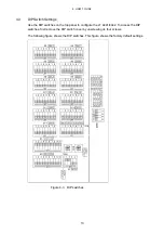
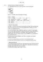
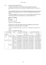
The settings are listed below. For details on each item, see the following sections in chapter 4.
A simple explanation of the settings is also printed on the back side of the DIP switch cover.
Table 4-1 List of settings
Setting Name
Remark
Factory
Default
CH-1
S3
All OFF
No signal selected
CH-2
S5
All OFF
No signal selected
CH-3
S8
All OFF
No signal selected
CH-4
S10
All OFF
No signal selected
CH-5
S12
All OFF
No signal selected
CH-6
S14
All OFF
No signal selected
CH-7
S4
All OFF
No signal selected
CH-8
S6
All OFF
No signal selected
CH-9
S9
All OFF
No signal selected
CH-10
S11
All OFF
No signal selected
Input signal settings
CH-11
S13
All OFF
No signal selected
VREF LOW
S1
All ON
Error detection reference settings
VREF HIGH
S2
All OFF
LOW
USER ADJUST1
RV1
-
-
Error detection level settings
(user-defined)
USER ADJUST2
RV2
-
-
S500 All
OFF
Signal switch time settings
ERROR DETECTION SPEED
S16 All
OFF
High speed
SW1: ON
NORMAL
SW2: ON
Approx. 1 minute
Operation mode and standby time settings MODE
S7
SW3, SW4: OFF
-
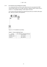
4.3.1 Setting
Method
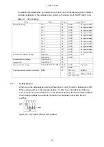
When one of the slide switches on the DIP switch is in the OFF position, that switch is OFF.
When a slide switch is in the opposite position, it is ON. Use an item that has a fine tip,
such as a pen or a pair of tweezers, to move switches between the ON and OFF positions.
When making settings, be careful to not touch any components other than the DIP
switches.
Figure 4-4 DIP switch ON and OFF positions


