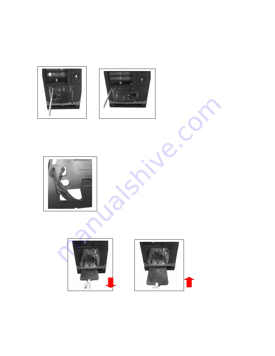
LC-POWER Gaming 978BG Скачать руководство пользователя страница 11

2.6

PSU installation

1.

Place the PSU in a proper location and fix it with the provided screws.


(Screw holes enable a PSU mounting from both sides; fan up or down)

2. Place the power supply cables behind the mainboard tray. 

3. To clean the dust filter, pull out the washable dust filter which is placed under 

the power supply location.


Содержание Gaming 978BG

Страница 1: ...User manual Gaming 978BG Tank Buster...

Страница 2: ...n guide 2 1 Side panel assembly 05 2 2 Motherboard installation 06 2 3 5 25 device installation 07 2 4 3 5 device installation 08 09 2 5 2 5 device installation 10 2 6 PSU installation 11 2 7 Fan inst...

Страница 3: ...al 3 5 drive bay 6 internal HDD cage with hot swap feature 2 5 drive bay 3 internal PCI slot 9 I O Panel 2x USB 3 0 2x USB 2 0 1x Audio 1x Mic fan speed control for up to 5 fans Control Panel Power sw...

Страница 4: ...Accessory Accessory box contents 1x user manual 1x screw bag Standoff Screw Screw Screw 5H 6 4 6 6 5HCu M3 5 6 5KM 3 8 8PWA 10PCS 20PCS 24PCS 4PCS Plastic hand screws Screw Cable tie Cable tie 6 32 6...

Страница 5: ...de 2 1 Side panel assembly 1 Remove the side panel Remove the screws on the back of the chassis and open the side panel 2 Reattach the side panel Align the side panel with hook holes to close the side...

Страница 6: ...motherboard installation bracket 2 Install the motherboard in a proper location and fix it with the provided screws Note CPU RAM and any peripheral installation steps are not included in this manual P...

Страница 7: ...evice installation 1 Press the latch to remove the 5 25 drive cover from the chassis by pushing it inside out Now put the 5 25 ODD into the drive bay 2 Fix the 5 25 ODD with the quick release screws o...

Страница 8: ...of the latch 2 Push the latch of the drive bay and take out the 3 5 drive bay tray 3 Place an HDD into the drive bay tray and secure it on the bottom of the tray with the provided screws Reverse the...

Страница 9: ...r supply Connect the backplane to the motherboard with the help of SATA cables Note The user may choose the direction of the 3 5 drive cage This will help the user to arrange the chassis placement fle...

Страница 10: ...he 3 5 HDD cage location 1 Open the side panel with the help of the latch 2 Place the 2 5 HDD SSD in a proper location as shown below and fix it with the provided screws 3 For the third position relea...

Страница 11: ...ix it with the provided screws Screw holes enable a PSU mounting from both sides fan up or down 2 Place the power supply cables behind the mainboard tray 3 To clean the dust filter pull out the washab...

Страница 12: ...ow and then remove the bottom bracket 2 Install the fan inside the chassis and secure the screws from the bottom side You can install maximum two 120 mm fans on the bottom panel Top panel fan installa...

Страница 13: ...tall maximum three 120 mm or two 140 mm fans on the top of the chassis 2 8 Water cooling installation On the back side of the case you will find pre drilled water cooling holes Screw holes are drilled...

Страница 14: ...5 HDD activity LED 6 Fan speed LED 7 USB 3 0 port 8 USB 2 0 port 9 Audio mic The chassis provides a fan speed control feature which supports up to 5 case fans Press the symbol to accelerate and the sy...

Страница 15: ...fan 1 Connect a 4 pin Molex PATA connector from PSU 2 Remove the top cover and connect the 3 pin fan connectors to the control board Please refer to the following illustration of the front I O connec...

Страница 16: ...Front I O Connector Motherboard Case cable connector USB 3 0 USB 2 0 AC 97 HD Audio...

Страница 17: ...will be handled by your dealer If the case is damaged due to improper operation the warranty period expires immediately Check www lc power com or contact us by e mail at support lc power com Silent P...

Отзывы: