Page 12
PROTECTOR® IV Gauge Face Installation, Operation & Maintenance Manual
13.
Secure the mounting bolts to the clamp blocks tightening the right bolt first to ensure the wiping bar is
pushed securely against the rail.
14. Occasionally tap the assembly as you are tightening to insure wiping bar remains tight to the rail.
15. Torque mounting bolts to approximately 200-250 ft.-lbs. (340 N-m).
Note: Tapping assembly with a hammer ensures the wiping bar remains in contact with rail gage face. Ensure
wiping bar remains tight to rail as mounting bolts are being tightened.
16. Install the wiping bar supply hoses, directing the free ends towards the central supply point. After tightening
the hoses, turn wiping bar inlet elbow slightly so that the supply hoses are directed smoothly downward
towards the top of the sleepers.
After full installation and initial testing the wiping bar should be assessed to check that it is set at the correct
height. As mentioned before, if the bar is set too high it is likely to be damaged by passing wheel flanges and
if set too low the lubricant will not be picked up properly by the wheel flanges. If either is the case, step #12
should be repeated to reset the height.
MC-4® XL Grease Bar Installation
The MC-4XL wiping bars are similar to the MC-4 bars, but have been
extended to 55” (1.4 m) length to provide additional distribution of
grease.
In a four bar arrangement, MC-4XL bars can only be installed on
tangent track. In a two bar arrangement, MC-4XL bars can be
installed early in the transition when two bars are to be installed
on one or both rails, they should be positioned end to end, or
as close as possible. This insures lubrication of the entire wheel
for maximum grease coverage. Install these bars using the same
instructions as provided on the configuration page. The only extra
requirement when installing the MC-4XL bars is that they should
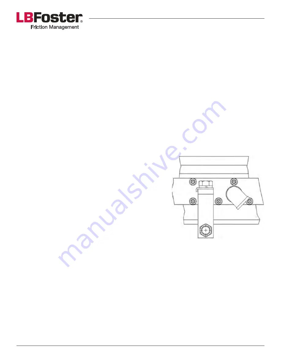
be installed with an extra clamp in the center of the bar to ensure
the bar is pushed fully against the gage face of the rail. Install this
clamp behind the curve of the inlet elbow to avoid obstructing the
inlet hose (see
Figure 3
). Once the wiping bars have been installed using the same procedure as described
earlier, the extra clamp can be secured to the rail and the rectangular spacer can be pushed against the middle
of the bar, then the mounting bolt secured to hold the spacer in place.
Distribution Hose Installation
Install one main supply hose and four grease distribution unit hoses as follows:
1. Run main supply hose from tank, underneath the rail, to a position central to wiping bar assemblies.
2.
Layout the “H” configuration of valves with main hose and distribution hoses.
3.
Thread the main supply hose to the “H” configuration of valves at center track.
4.
Thread each hose between “H” configurations of valves to an individual wiping bar.
Note: Hoses supplied by the customer must be non-conducting, this ensures the hose system will not shunt signals.
Figure 3: MC-4XL Center Clamp Position


