background image


14


OPERATING INSTRUCTIONS 
 

The ground speed will always vary depending on the particular operation being 
performed.  The Lewis Windrower 

II

 is designed to be operated with the tractor 

PTO turning within a range of 500 to 540 RPM.  540 RPM is the most desirable 
PTO speed.  Place the machine into operation by first engaging the PTO of the 
tractor with the tractor engine at a safe idle speed. 


IMPORTANT: ALWAYS ENGAGE PTO CLUTCH SLOWLY AND SMOOTHLY 
AT LOW RPM TO AVOID SUDDEN STARTS AND FAST CLUTCHING THAT 
CAN DAMAGE THE DRIVE COMPONENTS. 


Never operate the Windrower with anyone near the 

machine.  Never get off the tractor with the PTO Engaged.  Make sure that 
the area around the Windrower
 is clear before operation.


Storage 


  Be sure to clean and lubricate the windrower after each use and maintain 

all guards and decals.  Should any guard or decal be damaged or need 
replacing, contact your Lewis Brothers Dealer. 


LUBRICATION 


CAUTION

: Always look for hydraulic leaks with the tractor’s engine 

off.  Wear hand and eye protection.  Use cardboard or wood instead 
of your hands to search for a leak’s source. 
 

Grease the following points lightly each 50 hours and before 
storage. 

 
1. Cylinder 

Shaft 

Bearings 

 
Grease all chains and bearings after each use. 


ATTENTION: 


Be sure to keep drive chain well lubricated and free of 

obstructions to insure proper operation. 
 

Содержание WINDROWER II

Страница 1: ...1 LEWIS WINDROWER OWNER OPERATOR MANUAL MODEL WR 2 WINDROWER II Manufactured by LEWIS BROTHERS MANUFACTURING INC Post Office Box 146 Baxley GA 31513 Tel 912 367 4651 Fax 912 367 3958 1 20 2020...

Страница 2: ...t equipment is only as good as its operation and management Sound operation and good preventive maintenance practices are essential to efficient performance of your Lewis Windrower Questions on parts...

Страница 3: ...4 Owner s And Operator s Responsibility 5 General Precautions 6 WARRANTY 7 Limited Warranty 8 SPECIFICATIONS 9 Model WR 2 Specifications 10 SETUP AND OPERATION 11 Machine Setup 12 Operating Instructi...

Страница 4: ...4 SAFETY...

Страница 5: ...ety issues mentioned in this manual Lewis Brothers cannot anticipate all conceivable ways service and operational functions might be performed and of the possible hazardous consequences of such Anyone...

Страница 6: ...ition when parked and unattended STOP the tractor s engine and relieve any hydraulic pressure by actuating all hydraulic valves in both directions before disconnecting any part of the hydraulic system...

Страница 7: ...7 WARRANTY...

Страница 8: ...de without written approval of LBM will render this LIMITED WARRANTY void LBM s obligation specifically excludes any liability for consequential damages such as loss of profit delays expenses damage t...

Страница 9: ...9 SPECIFICATIONS...

Страница 10: ...10 SPECIFICATIONS Lewis Windrower Model WR II Width 8 ft 2 in Length 64 in Height 50 in Weight 1800 lbs Blade Width 93 in Aux Hyd Outlets 2 sets required Tractor hp creeper gear recommended 75hp...

Страница 11: ...11 SETUP AND OPERATION...

Страница 12: ...the Windrower to the tractor s three point hitch See Figure 1 and secure with the proper attachment pins Next attach the drive shaft to the PTO shaft on the tractor See Figure 2 Slide the drive shaft...

Страница 13: ...e Lewis Windrower II is designed to handle a maximum system pressure of 2500 PSI Excess pressure should be avoided in order to prevent damaging system components Tractors that are capable of supplying...

Страница 14: ...yone near the machine Never get off the tractor with the PTO Engaged Make sure that the area around the Windrower is clear before operation Storage Be sure to clean and lubricate the windrower after e...

Страница 15: ...15 PARTS...

Страница 16: ...300630 1 1 8 Hitch Pin 2 WR 300040 Right Lift Arm Mount Hydraulic Cylinder 3 WR 300120 Right Lift Arm Mount 4 WR 100028 Gear Box 5 WR 100025 Drive Shaft 6 HW 960330 Gear box mount bolt 12mm 1 75 x 20...

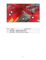
Страница 17: ...17 ITEM PART DESCRIPTION 1 WR 300015 Hydraulic Cylinder Spacer 2 HK 101253 Hydraulic Cylinder 3 x 6 3 WR 300008 Flow Divider Valve complete 2 3 2 1...

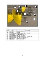
Страница 18: ...HW 208108G5Z Bolt Hex Head 1 2NC X 1 1 2LG 4 HW 335208Z Lock Washer Lock 1 2 5 HW 300208ZG5 Nut Hex 1 2 13NC 6 HW 212112G5Z Bolt Hex Head 5 8 11NC x 2 G5 ZP 7 HW 300212ZG5 Nut Hex 5 8 13NC ZP G5 8 HW...

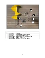
Страница 19: ...Top Auger 2 WR 300419 Four bolt flange bearing 1 5 8 Shaft 3 WR 300422 Two bolt flange bearing 1 5 8 4 HW 208112G5Z Bolt Hex Head 1 2 13NC x 2LG G5 ZP 5 HW 335208Z Washer Lock 1 2 ZP 6 HW 300208ZG5 Nu...

Страница 20: ...20 Item Part Description 1 HW 960330 Bolt Hex Head 12 MM 1 75 x 20MM LG ZP w shoulder 2 WR 100028 Gear Box 2 1...

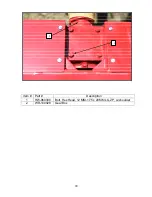
Страница 21: ...uard 8 WR 300600 Chain Roller Mount 9 HW 325216Z 3 4 USS Flat Washer ZP 10 HW 301212NEZ Nut Nylon Insert Lock Hex 5 8 11 Type ne 11 WR 300004 Sprocket 1 5 8 Bore 80 Chain Drive 12 WR 600084 Sprocket 8...

Страница 22: ...22 Item Part Description 1 WR 300130 Shaft and Yoke Weldment 2 WR 100026 U Joint 3 WR 100024 Torque Limiter 1 2 3...

Страница 23: ...23 DECALS HK 100916 HK 100899 HK 100912 WR 600061 HK 100908...

Отзывы: