Defender Press Brake Guarding System Operation Manual
LS-CS-M-069
Page 7
Original Language Version: 1.04
Released:
01/04/2020
These sensors are divided into three zones that represent the front, middle and rear of the
laser plane (the
FR
,
MI
,
RE
signals). If an obstruction blocks the laser light to any of the
sensors, the receiver will turn off the appropriate signal, and the PGS-2 controller will
immediately disable downward movement of the press beam.
3.3.2
Laser Classification and Warnings
Warning: CLASS 1 LASER DEVICE
The LZS-1 laser transmitter emits CLASS 1 planar laser light approximately
50mm in width. Do not stare directly into the laser or the transmitter window.
Warning: CLASS 3R LASER RADIATION: DO NOT OPEN OR TAMPER WITH
THE LASER TRANSMITTER
The LZS-1 laser transmitter contains no user serviceable components. Do not
attempt to tamper with, or dismantle the laser transmitter as this will void the
product warranty and may expose you to the internal laser emitter CLASS 3R
LASER RADIATION that has the potential to cause eye damage.
3.3.3
Setup
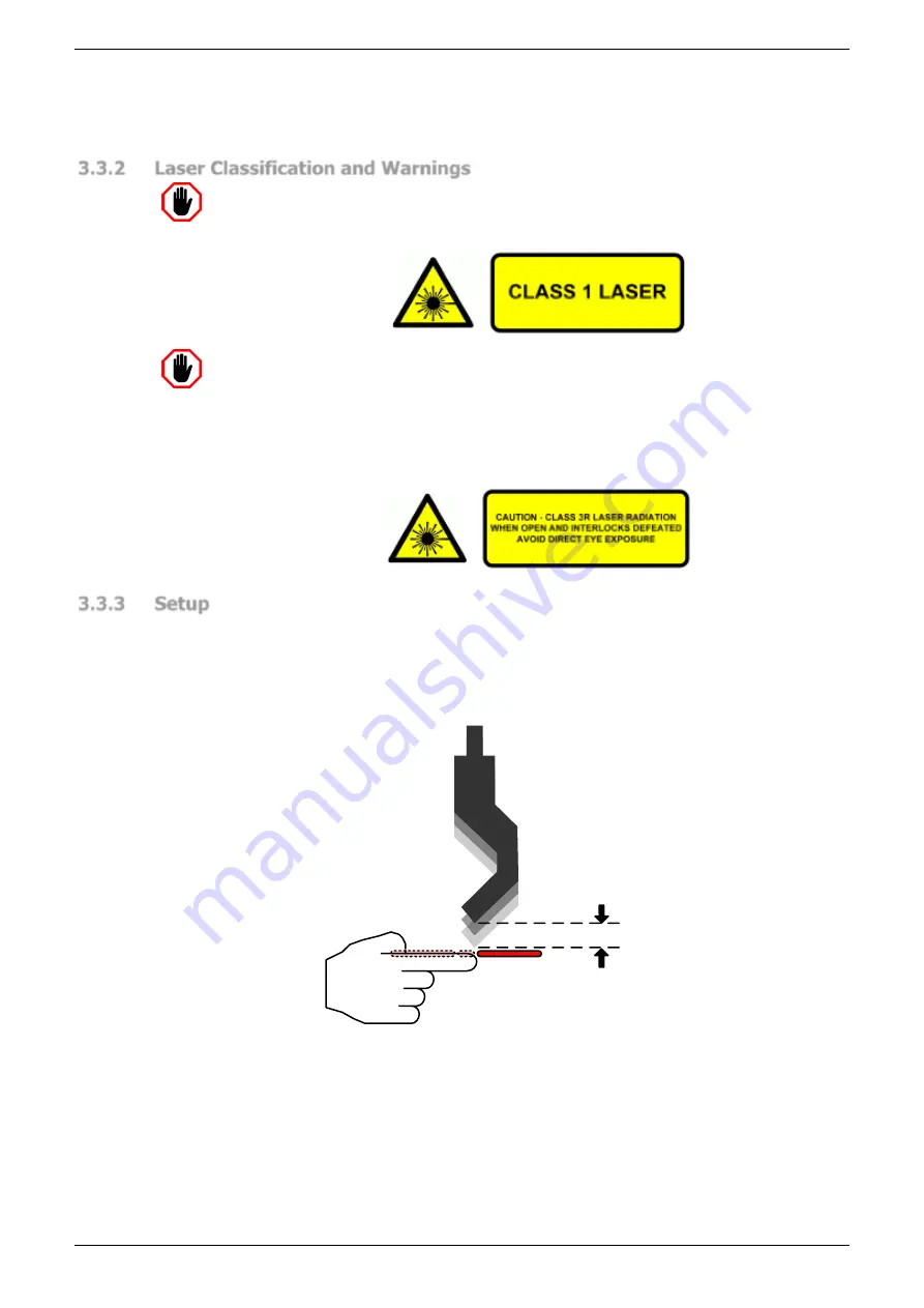
Prior to operating the machine, and after a tool change, it is necessary to check that the laser
is set to the correct distance below the punch tip. The laser to punch distance is configured
during installation of the system, according to the maximum stopping distance of the machine,
so that when an obstruction occurs the machine can stop before the tool tip reaches the
obstruction, see
Stopping
Distance
Figure 3-3: Stopping Distance
The stopping performance of the machine is measured by an overrun test at start-up, and is
automatically monitored relative to the laser to punch setting on every machine stop. If the
machine is operated continuously, the overrun test is repeated every 24 hours.
The laser to punch distance setting for your machine can be viewed in the Operator Panel by
navigating to the System Information screen (see
Section 5.7.1
MAIN
➔
INFO
➔
SYSTEM INFO


