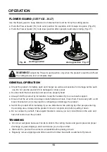
11
ASSEMBLY
• Press the release button (21) on the battery pack (5) and remove it from the product (Fig. 12).
• Align the battery pack (5) to the slots at the bottom side of the rear safety guard (2) and slide it in
until it locks in place (Fig. 13).
ATTACHING AND REMOVING THE BATTERY PACK
(SEE FIGS. 12-13)
Fig.12
Fig.13
• Unplug the line trimmer.
• Remove the spool from the line head.
• Insert the line into one of the two anchor holes found on the inside upper collar of the spool. Wind
the line around the upper part of the spool counterclockwise, as shown by the arrows on the spool.
Place line in the slot on upper spool flange, leaving about 5 in. (152 mm) extended beyond the slot.
Do not overfill. After winding the line, there should be at least 1/4 in. (6 mm) between the wound
line and the outside edge of the spool.
• Install the spool in the line head and replace the spool cover as described in Spool Replacement.
LINE REPLACEMENT (See figs. 10)
NOTE:
Remove any old line remaining on the spool. Cut the line being approximately
16.4ft
(
5m
)
long. Use only 0.065 in. (1.65 mm) diameter monofilament line.
Fig. 9
Spool Cover
Spool
Tabs
Eyelets
Slots
Fig. 10
Anchor Hole
Spool
Содержание 24LSC01-ETL
Страница 25: ...25 EXPLODED VIEW CLGT2410 EXPLODED VIEW...
Страница 27: ...27 NOTES...
Страница 51: ...51 VUE CLAT E VUE CLAT E DU MOD LE CLGT2410...
Страница 53: ...53 REMARQUES...


