DA11
Quickstart Guide
4
-
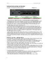
Pin 2 & Pin 3
. These settings determine the configuration of the output for balanced or
unbalanced operation. A typical use would be to set the outputs
to Pin 2 “On” and Pin 3 “Off”
when connecting the DA11 to a preamp with RCA inputs. This applies to the included adapters,
as well as most standard XLR to RCA adapters and adapter cables.
Please see CONFIGURING THE XLR OUTPUTS for details on the correct settings.
-
If pin 2 is “on” as indicated by the LED above the “pin 2” label, Pin 2 is active (has audio
signal present) on both the left and right output XLR connectors. If pin 2 is “off” as indicated by
the LED above the “pin 2” label, Pin 2 is grounded on both the left and right output XLR
connectors.
-
If pin 3 is “on” as indicated by the LED above the “pin 3” label, Pin 3 is active (has audio
signal present) on both the left and right output XLR connectors. If pin 3 is “off” as indicated by
the LED ab
ove the “pin 3” label, Pin 3 is grounded on both XLR connectors.
-
If either pin 2 or pin 3 is already “off,” setting the opposite pin to “off” will turn the first pin “on”
so that a least one pin is always active.
-
If both pins are “on,” the output is configured for balanced operation.
-
If pin 3 is “off,” the outputs are configured for “Pin 2 Hot unbalanced” operation.
-
If pin 2 is “off,” the outputs are configured for “Pin 3 Hot unbalanced” operation.
-
Dim
. This function sets the brightness level of
the front panel display. When dim is “on” as
indicated by the LED, the front displays are dimmed to approximately half brightness.
Diagram 1, Section 3- Sample Rate Display (Setting mode)
- In Setting mode this window displays the sample rate of a digital input that is valid and
“locked.” For standard sample rates of 44.1, 48, 88.2, or 96 kHz, the first two digits of the actual
sample rate are displayed, so an input that is locked to a valid 88.2 kHz sample rate would be
indicated by an “88” in the VOLUME display. Please see the OPERATION section of the
manual for details.
- In Setting mode if the DA11 is not receiving a valid signal on the selected input or there is
nothing connected, the symbol “- -” appears in the VOLUME display. This can be quite useful
when troubleshooting problems. For example: Why is no music coming from the DA11 outputs
when my computer (USB source) is playing a track in the player software? Please see the
section titled USB INPUT for more details.
Diagram 1, Section 2-
>PiC< Playba
ck Image Control™
(Operating mode)
This section controls the stereo image in both the main (XLR) outputs and the headphone
output. It
consists of the LED’s below the IMAGE legend (+2, +1, etc.) and the two switches
labeled “wide narrow” and “narrow wide.” Moving the settings in the “wide” direction increases
the apparent width of the stereo image, and moving the settings in the
“narrow” direction
decreases the stereo width (making it “more mono”). The left and right controls are
independent of each other, and can be used to alter the stereo image of asymmetric mixes
(true stereo recordings, for example) or adjust for asymmetrical speaker placement. When both
LED indicators are on “0,” the stereo image is not altered. Please note that the perceived
effects of these adjustments are very program dependent, and may result in a change in
acoustic volume level.
-
When “Mute” is activated from the optional infrared remote, in Operating mode
both
IMAGE
indicator LED’s will go dark to indicate that the Mute function is active.
- Please note that the switches are always active in both Operating and Setting modes, unlike
the LED indicators which change function depending on the mode.
Содержание DA11
Страница 4: ...DA11 Table of Contents ...


