background image

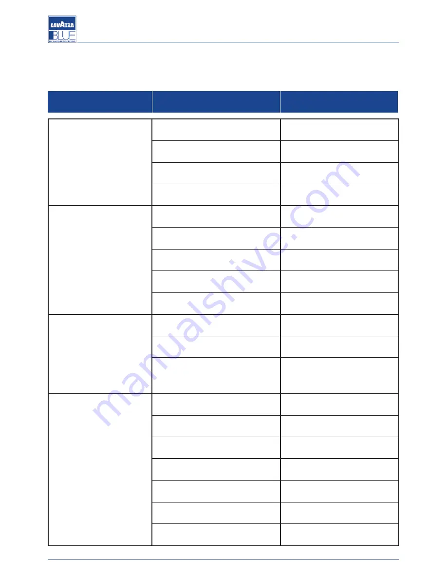
10. TROUBLESHOOTING

10.1. Signalling and solutions to the most common problems

PROBLEM

CAUSE

SOLUTION

No electrical power on the ma-

chine.

The on/off switch is placed to “0” position. Place the on/off switch to “I” position.

The on/off switch is damaged.

Replace the on/off switch.

The network switch is placed to OFF po-

sition.

Place the network switch to ON posi-

tion.

The connection to the electrical network

is defective.

Check for possible connection de-

fects.

No water in the boiler.

The valve of the water mains is closed.

Open the water mains valve.

The pump filter is clogged.

Replace the pump filter.

The power pump is disconnected or bloc-

ked.

Check the power pump.

The water inlet solenoid valve is dama-

ged.

Replace the water inlet solenoid

valve.

The filter of the water inlet solenoid valve

is clogged.

Clean or replace the solenoid valve

filter.

Too much water in the boiler.

The solenoid valve of the automatic level

device is damaged.

Replace the solenoid valve of the au-

tomatic level device.

The heat exchanger is perforated.

Replace the boiler.

The solenoid valve of the automatic level

device remains connected.

Check the level probe, the earth of

the frame and the operation of the

electronic control unit.

The machine does not dispense.

No water mains.

Check that there is water in the

mains.

The solenoid valve of the brewing unit is

defective.

Replace the solenoid valve of the bre-

wing unit.

The pump is jammed.

Replace the pump.

The fuse of the control unit is burnt out. Replace the solenoid valve protection

fuse (1A).

The injector is clogged.

Clean or replace the injector.

The brewing unit solenoid valve is clog-

ged or dirty.

Clean or replace the solenoid valve.

The flowmeter is jammed.

Check/replace the flowmeter.

22

Manual code 10066574 / Rel. 2.00 / February 2012

Maintenance manual for technical assistance

Содержание LB 2801

Страница 1: ...LB 2800 2801 2810 2811 MAINTENANCE MANUAL FOR TECHNICAL ASSISTANCE MANUAL CODE 10066574 REL 2 00 FEBRUARY 2012...

Страница 2: ...0118 LB 2810 Machine code 10080005 LB 2811 Machine code 10080023 Manual code 10066574 Rel 2 00 Edition 02 2012 www absoluteaftersales it Copyright LAVAZZA S p A Tel 0039 011 2348429 Fax 0039 011 23480...

Страница 3: ...s 7 3 HANDLING AND STORAGE 8 3 1 Handling 8 3 2 Storage 8 4 DISMANTLING AND DISPOSAL 8 4 1 Instruction for end of life treatment 8 5 INSTALLATION AND START UP 9 5 1 Unpacking 9 5 2 Positioning 9 5 3 W...

Страница 4: ...3 1 Cappuccinatore only LB 2800 LB 2810 models 20 9 3 2 Capsule holder 21 9 3 3 Steam pipe only LB 2800 LB 2810 models 21 9 3 4 Body 21 9 3 5 Steam pipe end only LB 2800 LB 2810 models 21 9 3 6 Brewin...

Страница 5: ...the personal protective equipment Warning WARNING messages are displayed before procedu res that if not observed could cause damage to the machine Environment ENVIRONMENT messages are displayed befor...

Страница 6: ...th 322 mm Height 470 mm Weight 31 kg 1 3 4 Technical specifications Power supply frequency 50 60 Boiler capacity litres 2 Boiler pressure bar 1 4 max Safety valve calibration bar 2 Supply water pressu...

Страница 7: ...ee brewing is taken directly from the heat exchanger During brewing cold water is sent inside of the exchanger by the pump Inside the heat exchanger cold water and the pre exi sting hot water are mixe...

Страница 8: ...hine must be put on the pipe 1 3 6 3 Automatic water entry system A E A The automatic water entry system checks the water level in the boiler The system is composed of a probe inserted in the boiler A...

Страница 9: ...uge with bottom scale greater than 9 bars to the specific fitting on the water circuit see the hydraulic diagram set the pressure by using the pressure adjusting screw located in the pump A in such a...

Страница 10: ...ions could cause accidents during machine operation and maintenance During the repair of the machine all the measures necessary to prevent ac cident must be used The main safety precautions that shoul...

Страница 11: ...the risks connected with operating and mainte nance machine conditions to be eliminated Lavazza re minds the user that the instructions procedures and recommendations contained in this manual should...

Страница 12: ...product should not be treated as a generic household waste but should be delivered to an authorised local recycling centre of WEEE Collecting the components of the machine in properly separated fracti...

Страница 13: ...ditions Attention Sufficient space must be allowed to access the ma chine and the plug to allow the user to move freely and to be able to immediately leave the area in an emergency Prepare a support...

Страница 14: ...Attention The hydraulic connection must be made in com pliance with local national rules If an external tank is used the connection pipe bet ween the machine and the tank must not exceed 150 cm For t...

Страница 15: ...e circuit so that the brewing units are completely heated Before using the machine dispense few coffees to check the operating pressure of the machine 6 RECOMMENDED TOOLS SET OF FIXED KEYS SET OF ALLE...

Страница 16: ...eat this operation for the other dose key When the programming is completed place the pro gramming lever 1 to the OFF position 7 2 2 Programming of cappuccino doses only LB 2800 LB 2810 models Put the...

Страница 17: ...crease cold water 7 2 4 Programming of coffee cappuccino sequence only LB 2800 LB 2810 models The machine allows you to decide which sequence to use when dispensing cappuccino In particular there are...

Страница 18: ...sed until the LEDs of the keyboard light up the flashing modes of the LEDs indicate the current temperature set temperature the sum of the flashes of every dose key multiplied by the indicated value s...

Страница 19: ...et quantity of water is reached dispensing stops automatically Attention Do not touch the hot water pipe because it is a com ponent which reaches high temperatures Dispensing steam only LB 2801 LB 281...

Страница 20: ...In the chart below milk temperatures related to the installed reducer are in dicated Temperature chart with and without flow reducers temperatures detected in a pre heated cup 7 2 10 Preparing coffee...

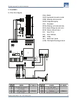
Страница 21: ...TED NOT INSERTED JP2 Pre infusion function enabled JP3 Programming key JP4 AEA pump coupling Coffee only Coffee only JP5 Tea key connector JP6 Tea pump coupling JP7 Continuous cycle operation JP8 Mixe...

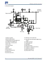
Страница 22: ...way valve 06 Drain tray 07 Pressure gauge 08 Reducer 09 Boiler 10 Brewing unit 11 Steam solenoid valve 12 Safety valve 13 Anti vacuum valve 14 Brewing unit solenoid valve 15 Solenoid valve of Automati...

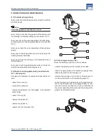
Страница 23: ...intenance 9 2 1 Brewing unit To replace the brewing unit components proceed as fol lows loosen the screw A remove the spring B replace the perforator C if damaged not compliant dispensing loosen the r...

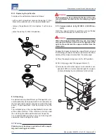
Страница 24: ...with comple tely clean and hygienic cloths Attention During cleaning be careful with the tips of the cap sule perforator located inside the clamping ring of the unit 9 3 1 Cappuccinatore only LB 2800...

Страница 25: ...ght so that the fatty coffee deposits can dissolve Then rinse them Warning If the capsule holders are not daily cleaned the qua lity of the dispensed coffee and the correct opera tion of the capsule h...

Страница 26: ...ean or replace the solenoid valve filter Too much water in the boiler The solenoid valve of the automatic level device is damaged Replace the solenoid valve of the au tomatic level device The heat exc...

Страница 27: ...gers and or the heating element Clean the machine The thermostat to protect the heating ele ment is trigged Reset the heating element protection Lime scale has reduced the water circu lation Clean the...

Страница 28: ...ged Controllare e pulire il gruppo eroga zione The capsule holder is dirty Check and clean the brewing unit Lower perforators are dirty Clean and replace the perforators if necessary The pressure gaug...

Страница 29: ...the dose is too small Check and replace the discharge val ves Water leakage from the unit solenoid valve during coffee brewing or when at resting position Clean and replace the solenoid valve if neces...

Страница 30: ...the power supply voltage of the motor is correct The pump works below the no minal capacity The inlet is clogged even partially Clean the pump filter The pump rotates in the wrong direction Check the...

Страница 31: ...wing Reduce the water temperature Air pockets in the hydraulic circuit Tighten fittings or connectors which are loose The flow reducer of the brewing unit is unsuitable Replace the flow reducer Manual...

Отзывы: