background image


- 5 - 

4.  METER INSTALLATION & RANGE CONSIDERATIONS


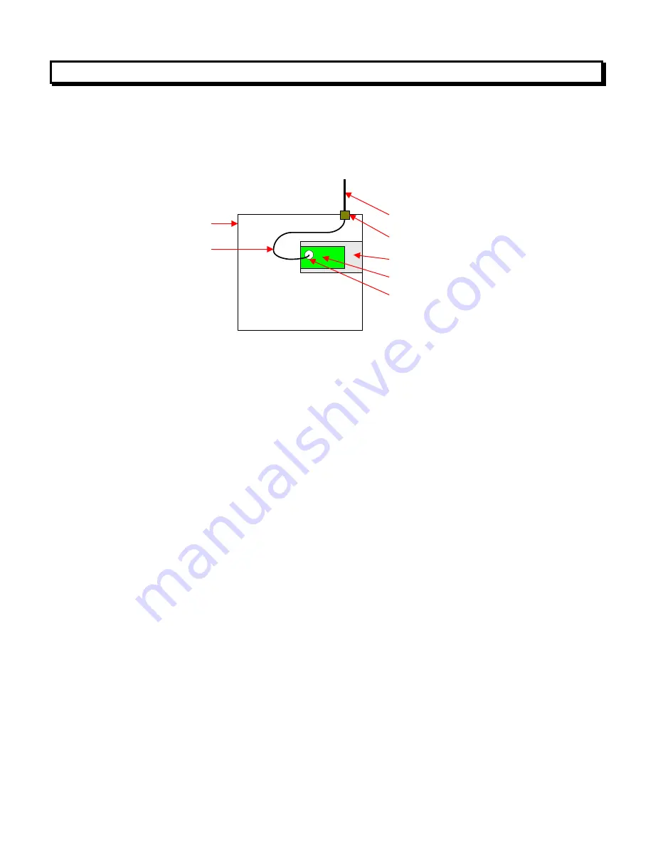
A meter with an LWIFI board,

 which has an integral antenna, needs to be mounted 

on a benchtop or in  a plastic enclosure that is transparent to  radio waves.  It is ideal 
for communication distances of 30 m (100 ft) or less. The presence of nearby circuit 
board traces reduces power radiated by LWIFI by about 10 dB compared LWIFIX. 

Male U.FL right-angle connector

Laureate digital panel meter

Omnidirectional antenna, 2.4  GHz

2.4 GHz LWIFX board

RP-SMA feedthrough

Metal electronics cabinet

Antenna cable assy,

760 mm (30)"


A  meter  with  an  LWIFIX  board, 

which  comes  with  an  external  antenna  and  a  760 

mm (30

”) long antenna cable, can be mounted inside a metal cabinet that blocks radio 

waves.  The  antenna  should  be  vertical  and  be  mounted  on  the  top  surface  of  the 
cabinet, which will then act as the antenna

’s ground plane and help shape an antenna 

pattern,  which  is  omnidirectional  in  the  horizontal  plane.  The  antenna  gain  in  the 
horizontal direction is 5 dBi. Also consider using LWFIX, as opposed to LWIFI, since it 
has about 10 dB higher output. 

WiFi  range 

depend  on  many  factors,  which  include  the  radiated  power  and  sensiti-

vities not only of the WiFi board but also of the WiFi router. Received radio power on 
either end is increased by the sum of gains in dB of both antennas. It is decreased by 
loss in dB of the antenna cable inside the cabinet and most significantly by loss in dB 
along  the  radio  path.  Every  -3  dB  reduces  power  by  a  factor  of  2.  Every  -10  dB 
reduces power by a factor of 10. 

WiFi  range 

can  be  90  m  (300  ft)  with  an  antenna  and  an  unobstructed  line-of-sight 

connection  outdoors,  but  it  is  half  of  that  or  less  indoors.  Substantial  signal  loss  is 
caused  by materials like  concrete,  bricks or plaster  that  absorb radio  waves, and  by 
nearby  metal  objects  that  reflect  and  scatter  radio  waves.  To  maximize  range,  mini-
mize  any  obstructions  between  the  WiFi  router  and  meter  antennas,  and  maximize 
antenna heights. If possible, place the WiFi router in a raised, central location to elimi-
nate WiFi dead zones. WiFi range is also reduced by interference from competing 2.4 
GHz  signals  from  other  WiFi  networks,  IoT  devices,  and  products  like  microwave 
ovens. 


Содержание LWFIX

Страница 1: ...LWIFI LWFIX Laureate High Speed Wireless Communications User Manual LAUREL Electronics Inc 3183 G Airway Ave Costa Mesa CA 92626 USA Tel 714 434 6131 Fax 714 434 3766 Website www laurels com...

Страница 2: ...3 3 Board Installation 4 4 Meter Installation Range Considerations 5 5 Network Setup Utility 6 6 Entry into Instrument Setup IS Software 9 7 Data Caching Data Rates Read Rates 11 8 Modbus Implementat...

Страница 3: ...or advantage of the two WiFi boards compared to legacy Laureate communication boards when used with data polling The legacy communica tions boards which include RS232 RS485 USB and Ethernet are limite...

Страница 4: ...y that the top and bottom edges of all circuit boards are at the same horizontal level If boards are inserted one electrical pin off this may burn out the electronics 2 Slide the electronics assembly...

Страница 5: ...consider using LWFIX as opposed to LWIFI since it has about 10 dB higher output WiFi range depend on many factors which include the radiated power and sensiti vities not only of the WiFi board but al...

Страница 6: ..._00 exe 500 kB from Laurel s software downloads web page or click here Copy the downloaded file into a directory of your choice and double click on the file name This will unzip the com pressed file i...

Страница 7: ...is ready to communicate with the outside world at 38400 baud using the discovered COM port The WiFi Signal Quality and IP address are still shown as No Connection because there is yet no WiFi connecti...

Страница 8: ...ay value peak value net value gross value display value Counter timer model numbers starting with L5 L8 alarm status display item 1 value peak value valley value item 2 value item 3 value Alarm and ov...

Страница 9: ...s the Device Type then click on RS232 USB for Communications Type since you IS software communications will be via USB In the resulting Establish Communications screen select the COM port discovered b...

Страница 10: ...10...

Страница 11: ...d by the measurement intervals of the meter Unchanged values are read by the external Modbus Master when data is read from cache at a rate faster than that at which readings are updated into cache Mea...

Страница 12: ...read or written If a 32 bit value is to be held in Holding Registers two 16 bit register addresses must be specified A Coil is a 1 bit memory location that is used to control a specific outcome It ma...

Страница 13: ...s Data Format FC04 0105 Read decimal point position 0001 xxxxxx 0002 xxxxx x 0003 xxxx xx 0004 xxx xxx 0005 xx xxxx 0006 x xxxxx FC03 7400 7401 Low address is most significant word High address is lea...

Страница 14: ...x 0004 xxx xxx 0005 xx xxxx 0006 x xxxxx FC03 7000 Alarm and overload status in bits 1 5 5 4 3 2 1 Bit 1 Alarm 1 Bit 2 Alarm 2 Bit 3 Alarm 3 Bit 4 Alarm 4 Bit 5 Overload FC03 7002 7003 Display measure...

Страница 15: ...Display value for analog DPMs Gross weight for scale meters Item 2 for counter timers FC03 7810 7811 Display value for analog DPMs Display value for scale meters Item 3 for counter timers 4 Reading a...

Страница 16: ...il Cold reset Latched alarms reset Peak value reset Remote display reset External Input B true External Input B false External Input A true External Input A false Valley reset Tare function Tare reset...

Страница 17: ...auses a meter reset Byte 3 Byte 2 Byte 1 Magnitude Mag XXXX XXXX XXXX XXXX XXXX XXXX S Sign Sign 1 for negative DP 1 for DDDDDD DP 6 for D DDDDD Sign Magnitude S M X XXX XXXX XXXX XXXX XXXX XXXX S Mag...

Страница 18: ...etpoint1 Byte 2 Serial Confg3 Deviation4 Byte 2 Deviation3 Byte 3 Deviation3 Byte 1 Setpoint4 Byte 2 Setpoint Byte 3 Setpoint3 Byte 1 Alarm Confg 3 M Type read only Analog Type Modbus Address Byte Dev...

Страница 19: ...fig2 Options Setup Alarm Config 2 Analog High Byte 3 Mag Mag Mag 2 s C 2 s C 2 s C Bits Byte Byte Byte Byte 2 s C 2 s C 2 s C Bits Mag Mag Mag Mag Mag Mag Mag Byte Bits Bits Mag Bits Bits Mag Mag Bits...

Страница 20: ...In1 Byte 2 2 s C 2 s C Mag Mag Mag 2 s C 2 s C S M 2 s C 2 s C S M 2 s C 2 s C 2 s C 2 s C 2 s C S DP M 2 s C 2 s C S DP M 2 s C 2 s C S DP M 2 s C 2 s C S DP M Analog Low Byte 3 Analog Low Byte 1 Dev...

Страница 21: ...1 Analog Low 2 High Reading 3 High Reading 1 High Input 2 Low Reading 3 Low Reading 1 Low Input 2 Offset 3 Offset 1 Scale Factor 2 Setpoint2 3 Setpoint2 1 Setpoint 1 2 Serial Cnfg 4 Spare Tare2 Spare...

Страница 22: ...int values 2 QModMaster Download and Launch Download QModMaster Win64 exe 0 5 3 beta zip from https sourceforge net projects qmodmaster files latest download and copy it into a directory of your choic...

Страница 23: ...23 b The second step is to click on Options Settings In the Settings dialog window ensure that everything is configured as shown and click on OK These are the default settings...

Страница 24: ...Modbus Mode TCP Function Code Read Holding Registers 0x03 Start Address 8200 dec Number of Registers 2 Data Format Float After QModMaster has been set up to read the floating point value Click on the...

Страница 25: ...rument s displayed value of 221 35 is read and presented in the main QMod Master window The values in holding registers 8200 and 8201 are combined to form a 32 bit value and are displayed in floating...

Страница 26: ...w presents the Modbus Command trans mitted to the LWIFI and its response Note that the hexadecimal values of 59 9A 43 5D represent the value in IEEE 754 floating point format little endian See Wikiped...

Страница 27: ...value The critical items are Modbus Mode TCP Function Code Read Holding Registers 0x03 Start Address 7400 Dec Number of Registers 2 Data Format Hex The Read Write icon has been clicked and the values...

Страница 28: ...28...

Страница 29: ...which is setup to read the alarm and overload status The critical items are Modbus Mode TCP Function Code Read Holding Registers 0x03 Start Address 7000 Dec Number of Registers 1 Data Format Binary Th...

Страница 30: ...30 The diagram below describes how each of the bits is interpreted...

Страница 31: ...31 You may wish to use the Windows calculator to convert two s complement values to decimal and vice versa...

Страница 32: ...izontal surface of metal cabinet USB interface USB 2 0 via mini USB connector WiFi Performance Wireless LAN standard IEEE 802 11 b g n Transmit receive frequency 2 4 GHz license free ISM band Maximum...

Страница 33: ...000 msec set for 60 or 50 Hz noise rejection Totalized pulse readings Signal period or gate time from 10 to 199 99 ms Frequency rate pulse readings Gate time 30 msec 1 2 signal periods Communication...

Страница 34: ...s 5 Mishandling or abuse The warranty set forth above is exclusive and no other warranty whether written or oral is expressed or implied Laurel specifically disclaims implied warranties of merchantabi...

Отзывы: