
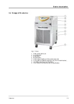


3.2 Design of the device
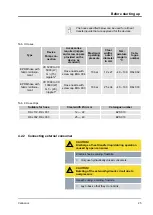
Fig. 1: Front
1
Filler nozzle with cover
2
Control panel
3
Manometer
4
Mains switch
5
Alarm output (interface 12N) and module slots
6
Front panel (ventilation openings only on air-cooled devices)
7
Ventilation openings (on both sides)
8
Four castors (front castors with locking brakes)
Device description
Variocool
15
Содержание VC 10000
Страница 47: ...Fig 13 Menu structure part 1 Operation Variocool 47 ...
Страница 48: ...Fig 14 Menu structure part 2 Menu structure for Graph Clock and Standby Operation Variocool 48 ...
Страница 103: ...General Variocool 103 ...
Страница 110: ......
Страница 111: ......


