background image

1200 Series User’s Manual 

3

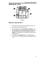
Setting the Time 

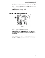
Figure 1 

Raise the Type Section 

1.  Unlock the case cover and pull it forward to remove it. 

2.  Wait until you hear the clock “click”. 

3.  Press either side of the 

Type Section Headlock – 1.2

and pull upward on the lower part of the Clock Face until 
the Type Section locks in the up position as shown in 

Figure 1

.  Note position of the Overthrow Lever and the 

Setting Wheel. 

4.  Press the red 

Overthrow Lever – 1.3

 away from you 

until it clicks.  This releases the wheels allowing them to 
turn.

Содержание 1221

Страница 1: ...888 534 5994 1221 USER MANUAL...

Страница 2: ...rvice information is also included in this manual in case any problems ever arise Thank you for choosing a Lathem time recorder Should you ever need assistance please let us know Ordering Accessories...

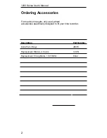
Страница 3: ...ng Accessories For maximum results only use Lathem accessories specifically designed to fit your time recorder Description Part Number Extra Pair of Keys JB976 Replacement Ribbon 2 Colors 7 2CN Replac...

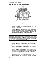
Страница 4: ...clock click 3 Press either side of the Type Section Headlock 1 2 and pull upward on the lower part of the Clock Face until the Type Section locks in the up position as shown in Figure 1 Note position...

Страница 5: ...rs are not underlined Set time to the proper hour of the day to avoid errors such as setting the day wheel to the next day at noon rather than midnight 3 Rotate the Minute Wheels to show the current m...

Страница 6: ...and verify the time and date or day is correct 9 Replace and lock the case cover Set the Time on the Clock Face Figure 3 1 Make a sample registration on paper 2 Rotate Clock Face Setting Wheel 3 1 unt...

Страница 7: ...type section see Raise the type section on page 3 2 Remove the cotter pins 4 1 that retain the ribbon spools and slide off old spools 3 Lift ribbon hold down guide 4 2 use pencil to support in up posi...

Страница 8: ...g you can easily remove and replace it with a spare without sending the entire machine for service Figure 5 1 Remove the top cover 2 Remove Type Section Retaining Ring 5 1 3 Lift type section slightly...

Страница 9: ...ne quarter of a turn counterclockwise 5 Remove the Motor Clutch 6 3 from its shaft The shaft has LEFT HAND threads remove clutch by turning clockwise 6 Hold Motor Bracket 6 4 and loosen Motor Mounting...

Страница 10: ...onsibility of Lathem under this warranty shall be limited to repair of this product or replacement thereof at the sole discretion of Lathem 5 If it becomes necessary to send the product or any defecti...

Отзывы: