background image

Operating Procedures

Anti-Scalp Wheel Adjustment

4

4-9

Lastec//021819

Operating Procedures

Содержание 100EFK

Страница 1: ...100EFK Lastec Mower Owner s Manual Manual Part Man 100EFK ...

Страница 2: ...his manual may be reproduced in any form by any photographic electronic mechanical or other means or used in any information storage and retrieval system without written permission from Lastec LLC 8180 W 10th Street Indianapolis IN 46214 Phone 317 892 4444 Fax 317 892 4188 www lastec com ...

Страница 3: ...ds And Covers 2 5 2 5 Pre operational Safety Rules 2 6 2 6 Operational Safety Rules 2 7 2 7 Maintenance Safety Rules 2 10 2 8 Storage Safety Rules 2 11 2 9 Hazard Identified Chart 2 12 SECTION 3 INITIAL SET UP 3 1 3 1 Assembly Instructions 3 2 3 2 Mounting The Articulator To The New Holland Tractor 3 2 3 3 Lift Arm Stop Bolt Adjustment 3 3 3 4 Transporting the Mounted Articulator 3 3 3 5 PTO Shaft...

Страница 4: ...Contours 4 7 4 8 Cutting Wet Grass 4 7 4 9 Anti Scalp Wheel Adjustment 4 8 SECTION 5 MAINTENANCE 5 1 5 1 Every 8 Operating Hours 5 2 5 2 First 8 Hours 5 3 5 3 First 50 Hours 5 3 5 4 Every 50 Operating Hours 5 3 5 5 Every 200 Operating Hours 5 3 5 6 Every 500 Operating Hours 5 4 5 7 Annual 5 4 5 8 Articulator Specifications Model 100EFK EFKC 5 4 5 9 Articulator Maintenance Chart Model 100EFK EFKC 5...

Страница 5: ...Lastec 021819 1 1 1 SECTION 1 TO THE OWNER ...

Страница 6: ...culator when children are present The information presented herein will prepare you to operate the Articulator in a safe and knowledgeable manner Proper opera tion of the Articulator will provide a safer working environment promote higher quality and provide more efficient results Keep this manual on hand at all times for ready reference The designed and tested safety of the Articulator is depende...

Страница 7: ...tec com or located in the back of this section This form must be completed and returned to the fac tory within fifteen 15 days of purchase in order to validate the warranty Please do not hesitate 1 3 If You Need To Order Parts To order parts contact your distributor Be sure to have your model and serial number available as a reference This will assist them in supplying you the correct and most cur...

Страница 8: ... under warranty at the warrantor s discretion After ninety 90 days component fail ure as a result of loose hardware is no longer covered under further warranty from warrantor Warrantor agrees to warrant for a period of ninety 90 days from date of purchase to any original purchaser who is a rental yard lease based business or temporary use facility that the equipment manufactured by warrantor and a...

Страница 9: ...sales aids shall constitute a warranty or other basis for any legal action against warrantor THE ORIGINAL PURCHASER ANY PERSONS TO WHOM THIS EQUIPMENT IS TRANFERRED AND ANY INTENDED USER OR BENEFICIARY OF THIS EQUIPMENT SHALL NOT BE ENTITLED TO RECOVER ANY CONSE QUENTIAL OR INCIDENTAL DAMAGES FROM WARRANTOR FOR ANY REASON WHATSO EVER INCLUDING WARRANTY OR DEFECT IN THE PRODUCT Warrantor does not w...

Страница 10: ...lly engineered and manufactured to provide safe dependable and satisfactory service As with all other mechanical equipment the Articulator requires routine inspection cleaning and maintenance When servicing the Articulator be sure to use only genuine Lastec parts Utilization of substitute parts will not only void the warranty but may also cause unsafe or unsatisfac tory operation of the Articulato...

Страница 11: ... of purchase Mower Model How did you hear about Lastec Who referred you to Lastec Date Purchased Distributor Dealer Purchased From How Did You Hear About Us Your Lastec Mower Average Operating Hours Total Acreage Cut Customer Profile Information I have read and understand the warranty policy and maintenance sections of the operators manual for the machine described below Who was the salesman that ...

Страница 12: ......

Страница 13: ...Safety Information Safety Information Lastec 021819 2 1 2 SECTION 2 SAFETY INFORMATION ...

Страница 14: ...l equipment hazard Failing to properly adhere to the instructions rules or procedures may result in personal equipment malfunction damage or destruction The above illustrated symbols are displayed throughout this manual in order to indicate important safety information When one of these symbols appears in this manual be aware of a potential hazard being discussed in the accompanying paragraphs Haz...

Страница 15: ... and Symbols Safety Information Lastec 021819 2 3 2 Caution Rotating Blades Keep Hands and Feet Away from Blades Keep Covers Locked Down Pinch Point Read the Manual Remove the Key Rotating Parts Rotating Shaft Stay Away Thrown Objects ...

Страница 16: ...s in this manual as well as all safety rules for any related equipment Although these instructions have been compiled through extensive field experience and engineering data some information presented herein may be general in nature due to unknown and or varying operating conditions However these instructions combined with your increasing experience with the deck will enable you to develop procedu...

Страница 17: ...er operate the deck without all covers shields safety devices and grass chute or mulching plate installed and secure Safety is a primary concern in the design and manufacture of all Lastec products Unfor tunately our extensive efforts to provide safe equipment can be negated by a single care less act of an operator In addition to the design and configuration of the deck hazard control and accident...

Страница 18: ...d the entire operator s manual to operate the deck Always wear relatively tight and belted clothing to avoid entanglement in moving parts Wear sturdy rough soled work shoes as well as protective equipment for the eyes hands hearing and head Never operate the deck or related equipment in bare feet sandals or sneakers Clear the cut area of stones branches balls or other debris that may be thrown and...

Страница 19: ...ance against accidents ALWAYS clear area of all personnel before operating the deck Only allow persons who have read and understand the entire operator s manual to operate the deck Be sure that the parking brake is set before attempting to start the engine Operate only in daylight or good artificial light min 200 Lux Operate the Articulator only from the operator seat Always wear ear protection wh...

Страница 20: ...nd deck Use extreme care and maintain minimum ground speed when transporting on a hill side or over rough ground and when operating close to ditches fences or water Reduce speed on slopes and in sharp turns to minimize potential tipping or loss of control Use caution when changing directions on slopes Be alert for holes in the terrain as well as any other hidden hazard Always drive slowly over rou...

Страница 21: ...ended If your drive unit is equipped with headlights and hazard lights always activate them whenever crossing or accessing any roadways driveways or parking lots Watch for oncoming traffic Handle fuel with caution it is explosive Always use approved fuel containers never handle fuel near an open flame never use fuel as a solvent never fuel the drive unit while the engine is running or hot never fu...

Страница 22: ...head and ear pro tection when performing any service or maintenance to the drive unit or deck Keep the drive unit engine area free of accumulated debris fuel or excess grease and oil to reduce fire hazard Keep the deck in good operating condition with all safety devices in place Check the blades frequently Verify that they are sharp free of nicks and cracks and securely fastened Periodically tight...

Страница 23: ...engine indoors Exhaust fumes are deadly Never store drive unit with fuel in the tank inside a building where fumes could reach an open flame or spark Allow the drive unit engine to cool before storing in an enclosed area Remove all accumulated debris from the drive unit and both the top and bottom of the deck before storing Sand chipped or scratched areas and re paint them to prevent rust during s...

Страница 24: ... using a PTO Guards are not in place Warning decals stating guards must be in place Physical guards around belts pulleys and shafts Clear warning in manual Danger of dismemberment Cutting blades Warning decals Clear warning in manual Physical guards around blades Clear prohibitions outlined in manual Danger of projectile strike Ejected debris from cutting blades Warning decals Clear warning in man...

Страница 25: ...Initial Set Up Initial Set Up Lastec 021819 3 1 3 SECTION 3 INITIAL SET UP ...

Страница 26: ...n level ground Be sure deck lift arms are in lowered position 2 Turn off the tractor disengage the PTO shift the transmission into neutral and set the parking brake Remove the key from the ignition 3 Approximate the position of the Articulator in front of the tractor 4 Attach the Articulator push arms to the tractor Secure with clevis pins 5 Attach the push arms to the Articulator Secure with bolt...

Страница 27: ...mower deck cutting height is low ered To adjust the lift arm stop bolts 1 Loosen the jam nut securing the lift arm stop bolt 2 Turn the lift arm stop bolt clockwise to increase the distance between the stop bolt head and the edge of the plate Turn the lift arm stop bolt counterclockwise to decrease the dis tance between the stop bolt head and the plate 3 Tighten the jam nut to secure the lift arm ...

Страница 28: ...O shaft shorter or avoid this area when cutting 6 If the PTO shaft can be easily reconnected then your maximum compression is within the proper range of your PTO shaft Now you will need to check the maximum extension of your PTO shaft 7 Drive the tractor over the mound Stop with the tractor headed down one side of the mound and the Articulator headed up the other side at the point where the PTO sh...

Страница 29: ...7 Mower Deck Height Adjustment The Model 100EFK EFKC Articulator can be set to various heights ranging from 1 to 4 3 4 Change the mower deck height at all the wheel locations by moving the wheel spacers from above to below each wheel yoke collar on each wheel yoke shaft When there are no wheel spacers located below the collar the deck is set at 1 There are two types of wheel spacers 1 thick and 1 ...

Страница 30: ... one inch when only one spacer is in front of the lever lock bracket and the middle deck idler spacers are located in the top position Each adjustable spacer on the adjustment rod placed in front of the lock bracket raises the deck height by 1 4 up to 4 3 4 The spacers which mark the 2 3 and 4 deck height positions are knurled for quick identification 1 Set the deck height adjustment wheel lock sp...

Страница 31: ...ional or replacement spacers may be obtained from your Lastec dealer if necessary 5 Adjust the rear wheel lock spacers to remove any excess slack by loosening the jam nut adjusting the rod on wheel lock arm until any slack in the rod is taken up and then tight ening the jam nut 6 Continue with the other decks until all decks have been adjusted 7 Remove the 2 blocks from under the blades 8 Re measu...

Страница 32: ...perly adjusted they can fail within a few hours Be aware that over 50 of the total belt stretch will occur within the first few hours of use The deck drive belts are located between the gearbox and the center mower deck under the center deck belt cover To access the belts remove the hardware and lift the cover from the deck The spring loaded idler automatically tensions the belts Check the belts f...

Страница 33: ...ion after 2 hours of operation Check all belt tension adjustment hardware after the first 8 hours of operation Again the overall life of the Articulator drive and deck belts is more greatly affected by the attention given them within their initial 8 hours of use than at any other time Properly adjusted the belts can perform over 1000 hours of service Improperly adjusted they can fail within a few ...

Страница 34: ...ulator If you are unable to install a new belt with the idler system at its minimum stroke it is likely you are installing the wrong size belt Contact your Lastec dealer for proper belt lengths for your Articulator Be sure that each idler pulley tensioning spring is properly installed and in good condition If for some reason this spring becomes loose detached or fatigued the idler will not properl...

Страница 35: ...way to the blades while the engine is running ALWAYS disengage the blades turn off the tractor remove the key and set the parking brake before attempting to inspect adjust change or perform any other maintenance to the blades Keep all personnel clear of all controls while inspecting adjusting changing or perform ing maintenance to the blades Inspect all blades for proper installation orientation t...

Страница 36: ...ot swivel freely clean and grease the shaft collar assembly Replace the bushings if necessary Grease each wheel after 8 hours of use and replace any worn or damaged tires 3 13 General Verify that all warning decals are in place visible and legible Verify that all covers and safety devices are properly installed and fastened Check that the discharge chute is clear of debris properly mounted and in ...

Страница 37: ...on Clean the entire center deck area including under the belt cover of all grease oil fuel grass or debris Be sure to replace all covers shields and guards Check all deck belts for proper tension Clean each entire deck area including under the belt covers of all grease oil fuel grass or debris Be sure to replace all covers shields and guards Inspect all blades for proper installation orientation t...

Страница 38: ...Lastec 021819 4 1 4 SECTION 4 OPERATING PROCEDURES ...

Страница 39: ...draulics to fold up the two outside decks allowing easy transporta tion This feature has many other benefits including remote operation access across narrow bridges through gates or doorways and reduction of required storage space For long term storage or long distance transportation use the safety pins on the outer decks to keep the decks in the upright position See Section 3 8 for details on usi...

Страница 40: ...e leveled from the Lastec factory Should deck leveling be necessary during maintenance see the section on Mower Deck Leveling Adjustment in the Set Up section of this manual 1 Disengage the PTO DANGER Always wait for all motion to stop after disengaging the PTO shaft Failure to do so may result in serious injury or death 2 Lift the drive unit 3 point hitch raising the Articulator 3 Slowly engage t...

Страница 41: ...iculator The Articulator is designed specifically for finish mowing applications One of the unique benefits of the Articulator s cutting system is its ability to float over contours that are impossible for other wide area mowers to cut accurately The Articulator offers a high level of maneuverability Although the Articulator is an industrial quality mower do not attempt to use it to cut extremely ...

Страница 42: ...ng brake and carefully begin cutting 4 4 Recommended Blades Ultra Low Blade Part No 063265 Use Ultra Low Lift Blade when the conditions are dry and in sandy soil areas When con ditions like this are evident lift created by the cutter blades can be reduced decreasing the abrasion wear to the cutter blades and deck caused by sand The Low Lift Blade will also help reduce cutter deck blowout during th...

Страница 43: ...o 5 MPH Your speed may vary within this range as your cutting conditions vary Excessive ground speed while trav eling over rough terrain can cause the Articulator to bounce excessively which in turn increases the stress on its structure and the likelihood of damage to the machine Thus while a higher ground speed is acceptable for wide open flat areas a slower ground speed is required for rough or ...

Страница 44: ...Articulator will be able to handle the area When cutting extreme contours always use a drive unit equipped with a ROPS and always wear your seat belt Following are important guidelines to follow when cutting extreme contours or side hills Never exceed the drive unit manufacturer s maximum side slope ratings Always use a drive unit equipped with a ROPS Always wear your seatbelt Do not operate the A...

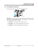
Страница 45: ...TANT Any time the mower deck height is adjusted on the Articulator it is neces sary to check all the anti scalp wheels for proper positioning The recommended anti scalp wheel height settings are as follows Deck Height 2 Set the anti scalp wheels to the top hole Deck Height 2 to 3 Set the anti scalp wheels to the center hole Deck Height 3 Set the anti scalp wheels to the bottom hole 120_140 1 ...

Страница 46: ...Operating Procedures Anti Scalp Wheel Adjustment 4 4 9 Lastec 021819 Operating Procedures ...

Страница 47: ...Maintenance Maintenance Lastec 021819 5 1 5 SECTION 5 MAINTENANCE ...

Страница 48: ...dware is functional securely fastened and in good condition Grease all wheel hubs Grease the PTO shaft collar and both cross bearings Inspect all belts for cracks wear or damage replace as needed Inspect the spindle bearing grease seals under each deck for grease leakage or improper seating Inspect gearbox and seals for leaks Verify that the split tapered bushing bolts mounted in the drive pulley ...

Страница 49: ... gearbox lube with 75W 90 gear oil 5 4 Every 50 Operating Hours Check deck alignment and belt tension Check deck drive belt alignment Grease all blade spindle bearing housings Fill until grease purges from the weep hole in the side of the bearing housing Inspect all bushings for wear Replace as needed Inspect gearbox pivot stop bolts wear pad and bushings Replace or adjust as needed Check and clea...

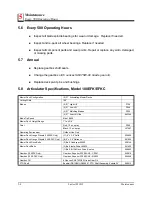
Страница 50: ...ing Width 100 Blades 5 21 High Lift P128 5 21 Low Lift P246 5 21 Mulching Blades P322 5 21 Low Lift Ultra 063265 Blade Tip Speed Max 16 600 Mower Deck Height Range 1 to 4 3 4 Paint Red 12 oz spray P299 Black 12 oz spray L07467 Operating Environment Outdoor Use Only Mower Deck Gauge Wheels 100EFK Only 11 9 x 3 5 Solid 056600 Mower Deck Gauge Wheels 100 EFKC Only 8 9 x 3 5 Reliance 061826 Mower Deck...

Страница 51: ...d Tools or Other Hazards Perform the Appropriate Maintenance Procedures Listed In Your Tractor Manual Verify grass chutes cleared Clean lube retighten all guide wheels Lubricate the PTO Quick Disconnect Pin or Twist Sleeve Check deck alignment and belt tension Check drive belt alignment Inspect gearbox pivot stops wearpads and bushings Clean off any debris that has accumulated Check bolts holding ...

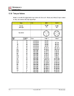
Страница 52: ...1 18 10 16 9 14 8 in lbs Nm in lbs Nm in lbs Nm in lbs Nm in lbs Nm in lbs Nm in lbs Nm ft lbs Nm ft lbs Nm ft lbs Nm ft lbs Nm ft lbs Nm ft lbs Nm ft lbs Nm ft lbs Nm ft lbs Nm ft lbs Nm ft lbs Nm ft lbs Nm ft lbs Nm ft lbs Nm ft lbs Nm ft lbs Nm ft lbs Nm 20 2 3 24 2 7 35 4 0 40 4 5 50 5 7 95 10 7 95 10 7 17 22 6 20 27 1 30 40 7 35 47 5 50 67 8 55 74 6 75 101 7 85 115 3 105 142 4 115 155 9 150 2...

Страница 53: ...C Maintenance Lastec 021819 5 7 5 5 11 Lubrication Points Model 100EFK EFKC See Figure 5 1 The Articulator lubrication points are shown below Idler Idler Idler 100_050 IMPORTANT Each wheel also has a fitting to be greased every 8 hours of operation ...

Страница 54: ...ort ant that the spacers remain tight between the frame work at all times Failure to keep these spacers tight will result in premature wear on the bolts and equipment damage Ensure that ALL bolts associ ated with urethane bushings are tight at all times In some cases urethane bush ing applications are associated with grease points The grease in these cases is used to pro tect the moving parts from...

Отзывы: