background image


PLMNL0232 REV. H Effective Date: 01/14/19 

41


FiberCUT

®

 2D Operation Manual 


5.3.2 Servicing the Upper Cover Glass 


REMOVING THE UPPER 
COVER GLASS DRAWER 
RUNS THE RISK OF THE 
FOLLOWING: 


Contamination in the 
collimating optics and/or 
fiber. 


Possible destruction of the 
collimating optics and/or 
fiber.  
 

ONLY REMOVE THE UPPER COVER 
GLASS DOOR WHEN: 


The fiber has been removed.  


The upper cover glass 
experiences a temperature 
fault. 


1.  Clean the outside of the head 

according to 

Section 5.1


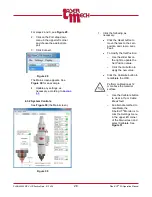
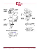
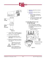
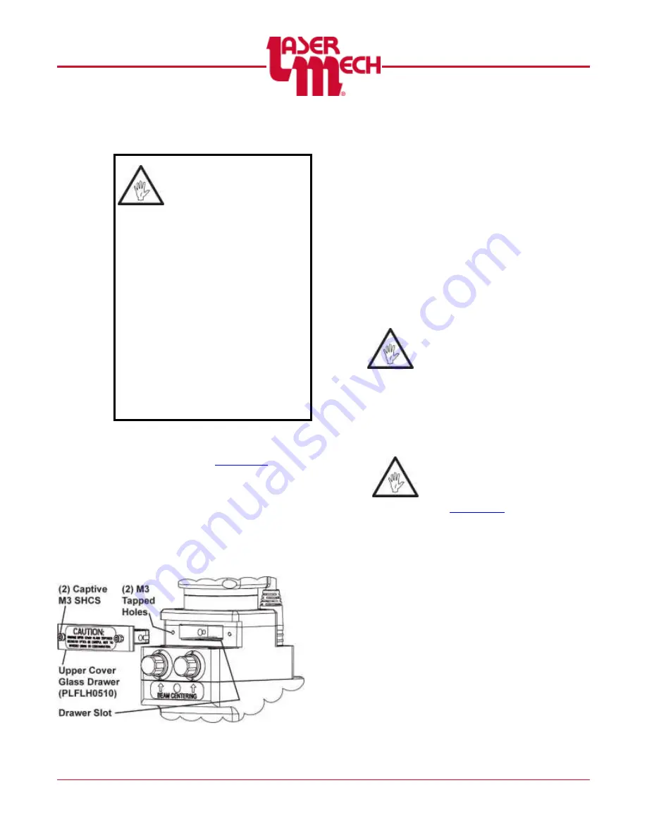
For steps 2 and 3, see 

Figure 54


2.  Loosen the (2) captive M3 

SHCS securing the upper cover 
glass drawer (PLFLH0510) to 
the head. 

3.  Pull the drawer straight out to 

remove it from the head.  


Figure 54


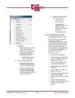
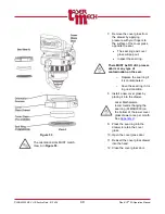
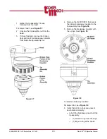
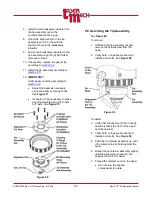
For steps 4 to 7, se

Figure 55


4.  Protect the cover glass with 

blue painter’s tape, or 
equivalent, and take to a clean 
area. 

5.  Remove the cover glass from 

the drawer by applying 
pressure with your fingers to 
the surface of the cover glass, 
opposite the seal. 


The seal ring and cover 
glass will pop out. 


Inspect the seal ring. 


There MUST be NO dirt, process 
debris or any type of 
contamination on the seal. 
 

o


Replace the seal ring if 
it is contaminated. 

o


Save the seal ring if it is 
in good condition. 

Laser Mechanisms recommends 
changing the seal ring 
(PLMSR0030) on the upper lower 
cover glass 

EVERY

 time you 

replace the upper cover glass. 
See 

Appendix H


6.  Install a new cover glass by 

placing it into the drawer. 


Содержание FiberCUT 2D

Страница 1: ...FiberCUT 2D Operation Manual ...

Страница 2: ...with furnishing performance or use of this product Laser Mech is a registered trademark of Laser Mechanisms Inc Corporate names and trademarks stated herein are the property of their respective companies COPYRIGHT 2019 Laser Mechanisms Inc All rights reserved No part of this publication may be reproduced in any form or by any means without the prior written permission of Laser Mechanisms Inc PRODU...

Страница 3: ...packaging material including the sealed padded pelican case in the event the head requires shipping or storage Check all items received against the packing list to verify that all the items were received Please note the product you receive may differ slightly from the illustrations in this manual While the drawings may differ the basic procedures described within remain the same TERMS USED IN THIS...

Страница 4: ...onnections 17 3 2 Generation 1 Controllers 19 3 2 1 Interface Example 19 3 2 2 Terminal Block Connections 20 3 3 Generation 2 Controllers 21 3 3 1 Interface Example 21 3 3 2 Terminal Block Connections 22 3 3 3 Industrial Ethernet Connection 23 3 3 4 Machine Sequence to Move the Lens to the Desired Location 23 3 4 Control Box Mounting 24 3 5 Control Box Indicator Lights 24 3 6 Electrical Grounding ...

Страница 5: ...ed 35 4 5 FiberCUT Monitor System Identification Information 36 5 Service 37 5 1 Cleaning the Outside of the Head 37 5 2 Servicing the Gas Jet Tip 37 5 3 Servicing the Cover Glasses 38 5 3 1 Servicing the Lower Cover Glass 39 5 3 2 Servicing the Upper Cover Glass 41 5 4 Servicing the Breakaway Insulator 42 5 5 Servicing the Tip Assembly 44 5 6 Servicing the Focus Lens 45 5 7 Adjusting the Focus Le...

Страница 6: ...dix D Nozzle Cooling and Air Blast Specifications 54 12 Appendix E Industrial Ethernet Data Mapping and Descriptions 55 12 1 EtherNet I P I O Mapping 55 12 2 PROFINET I O Mapping 56 12 3 Input Output and Other Descriptions 57 13 Appendix F Recommended User Serviceable Parts List 59 14 Appendix G Servicing the Tip Assembly 62 14 1 Rebuilding the Tip Assembly 62 14 2 User Serviceable Parts List 65 1...

Страница 7: ...ions for water cooling purge assist gas nozzle cooling and air blast Optional collimator cooling block not shown Multiple focus lens options 125 mm 150 mm or 200 mm Multiple collimating lens options 60 mm 80 mm or 100 mm Standoff distances from 0 2 8 0 mm Power rating up to 8kW Fully sealed and purged design to prevent contamination Sealed access doors prevent contamination during cover glass serv...

Страница 8: ... types of industrial fiber QBH HLC 8 QD LLK D LCA Q5 LLK B and PIPA Each of these fibers requires a unique fiber input adapter Refer to the fiber manufacturer s information for specific instructions ALWAYS position the fiber so it is horizontal during installation and removal See Figure 3 Figure 3 The fiber input adapter MUST be plugged or covered with tape when the fiber in not installed EVERY TI...

Страница 9: ...te steps 5 to 7 may result in damage to the fiber 5 Remove the protective covers on the fiber receiver and fiber end 6 Inspect the fiber end according to the fiber manufacturer s instructions 7 Install the fiber according to the fiber manufacturer s instructions For steps 8 to 10 see Figure 4 8 Align the upper fiber clamp so The 2 alignment holes are in line with the alignment pins in the fiber cl...

Страница 10: ... the fiber connection 1 If necessary remove the upper fiber clamp according to Section 2 2 1 2 If it is not already position the head so it is horizontal See Figure 3 For steps 3 and 4 see Figure 5 3 Loosen the 4 captive M4 SHCS securing the lower fiber clamp 4 Remove the lower fiber clamp and fiber clamp body Figure 5 For steps 5 to 7 see Figure 6 5 Loosen but do not remove the 4 M4 SHCS in the r...

Страница 11: ...e in line with the 2 alignment pins in the fiber clamp body 9 Tighten the 4 captive M4 SHCS loosened in step 2 Tighten the 2 SHCS on one side of the clamp one turn Tighten the 2 SHCS on the other side of the clamp one turn Repeat the process until the SHCS are tight on both sides 10 Verify the gap between the lower fiber clamp and the fiber clamp body is the same on both sides of the lower fiber c...

Страница 12: ... A See the manufacturer s information for specifications on cooling the fiber Assist gas specification are in Appendix B Figure 7 Purge gas specifications are in Appendix C Air blast and nozzle cooling specifications are in Appendix D For some applications Laser Mechanisms recommends additional cooling near the collimator In those cases a collimator cooling block PLSBW0101 replaces the standard el...

Страница 13: ...re or equivalent 1 Download and install the latest version Plugable 250X Digital USB Microscope software to the appropriate computer http www lasermech com productupdates The Plugable com website also has the software available to download and videos with more details on the features and uses of the microscope 2 Verify the high power beam is disabled 3 Thread on a gas jet tip with a 2 mm or larger...

Страница 14: ... the top of travel 11 Adjust the beam centering knobs on the head see Figure 11 so the beam is centered in the nozzle orifice Figure 11 The image on the screen should be similar to Figure 12 Figure 12 Beam is centered It is sometimes helpful to rotate the camera while it is seated against the tip assembly nut to confirm the beam centering 12 Move the focus lens from top of travel to bottom of trav...

Страница 15: ... slightly loose Centering in the X and Y direction should be adequate when the 3 sides of the electronic box and collimator body are flush as shown in Figure 15 If necessary it is possible to make small adjustments to center the beam by moving the collimator body If desired move the collimator body slightly in the X and or Y direction 14 Move the focus lens from bottom of travel to top of travel a...

Страница 16: ...nifying glass are highly recommended If necessary Laser Mechanisms offers an alternative solution See Section 2 4 1 Beam Centering Camera To manually center the beam in the gas jet tip 1 Verify that the high power beam is disabled 2 Put a piece of translucent tape on the end of the gas jet tip 3 Turn on the laser s internal red pointing beam and observe the position of the beam on the tape If the ...

Страница 17: ...ts the cutting head and any control box See Figure 17 Figure 17 1 Insert the female end of the control cable into the cutting head See Figure 17 For steps 2 to 6 see the chart below for the appropriate control box image Generation Refer To 1 Figure 18 2 Figure 19 2 Insert the male end of the control cable into the 14 pin connection on the control box 3 Connect the user supplied 24V DC 0 5A power s...

Страница 18: ...PLMNL0232 REV H Effective Date 01 14 19 18 FiberCUT 2D Operation Manual Generation 1 Control Box Figure 18 Generation 2 Control Box Figure 19 ...

Страница 19: ...ers 3 2 1 Interface Example The control box interface allows control and feedback of all the FiberCUT 2D operations The interface example in Figure 20 is applicable for the following Generation 1 Laser Mechanisms controllers Figure 20 Controller Description PLCSA0041 PROFINET PLCSA0052 EtherNet IP ...

Страница 20: ...nearly from 0 to 30mm 500mbar or 100 C depending on the assigned function GND Analog Ground Proc Out The Process Monitor output is a signal 0 10V indicating the status of the laser cutting process Interpretation requires significant processing with the user s machine to determine pierce through and loss of cut values GND Analog Ground Figure 21 There are 3 digital outputs Ready Touch and In Pos av...

Страница 21: ...ox interface allows control and feedback of all the FiberCUT 2D operations The interface example in Figure 22 is applicable for the following Generation 2 Laser Mechanisms controllers Figure 22 Controller Description PLCSA0064 Discrete I O with EtherNet IP PLCSA0065 Discrete I O with PROFINET PLCSA0066 Discrete I O no Industrial Ethernet ...

Страница 22: ...ndicates the status of the laser cutting process Interpretation requires significant processing with the user s machine to determine pierce through and loss of cut values GND Analog Ground Figure 23 There is one analog input Lens In available through the terminal block ANALOG INPUT INPUT DESCRIPTION Lens In The Lens In signal 0 10V is used to specify the target position of the lens The input is sc...

Страница 23: ...n Position turns on Lens In 3 3 3 Industrial Ethernet Connection The Industrial Ethernet interface provides extensive control and monitoring of the FiberCUT 2D Depending on the control box model either EtherNet IP or PROFINET communications protocol is used See Appendix E for details on device configuration and available data 3 3 4 Machine Sequence to Move the Lens to the Desired Location See Sect...

Страница 24: ...ER is green and illuminated when power is supplied to the control box The indicator light labeled READY is illuminated in green when the READY output is active The light illuminates in red when a fault is detected within the head The indicator light labeled TOUCH is green and illuminated when the tip is in contact with the part or another conductive surface The indicator lights labeled A B C and D...

Страница 25: ... Online PLC in STOP CLEAR Red EtherNet IP Duplicate IP address detected PROFINET Internal error Red and Flashing EtherNet IP One or multiple connections has timed out 3 6 Electrical Grounding and Noise The capacitive height sensing circuitry contained in the FiberCUT 2D cutting head measures small changes in electrical capacitance between the tip and earth ground to determine tip to part standoff ...

Страница 26: ...Download the latest copy of FiberCUT Monitor 2D from the FiberCUT Updates web page http www lasermech com fibercut2dupdates Once the compressed folder is downloaded from the web site it only needs to be decompressed 1 Right click on the compressed folder and select Extract All 2 Follow the on screen instructions to complete the decompression extraction of the compressed files The resulting folder ...

Страница 27: ...are 4 Click on the Browse button 5 Locate and open the folder containing the FiberCUT Monitor software open the Driver folder click on the FiberCUT 2D folder and then click OK 6 Click on the Next button 7 A security message may appear warning that Windows can t verify the publisher of this driver software 8 If this happens click on Install this driver software anyway 9 The driver should now instal...

Страница 28: ...30 1 Click the following as necessary Click the Reset button to move the lens to the zero position and clear a Lens Fault To modify the Set Position o Use the slider bar on the right to update the Set Position value o Click the Go button to apply the new value Click the Calibrate button to recalibrate the HSU Perform calibration at 12 mm above the material surface o Use the Calibrate button to cle...

Страница 29: ... monitor focusing lens and nozzle o Purge gas pressure 4 3 3 Faults and Status Indicator See Figure 30 the Main screen When a fault occurs the Ready output turns off and the corresponding light on the control box turns red A description of the fault is also displayed in red in the upper right corner of the Main screen and the module responsible for the fault will be highlighted on the diagram of t...

Страница 30: ... See Section 4 1 for details This section lists the settings that must be specified before operating FiberCUT 2D Before adjusting any settings The software must be installed on your PC See Section 4 1 for more details The head and control box must be connected properly See Section 3 1 for more details 4 4 1 Unlock Settings 1 Click the Settings menu in the upper left corner of the Main screen and s...

Страница 31: ...corner of the Main screen and hover over HSU Curve 2 Click Linear Optimized or Other as desired Figure 35 Load Curve and HSU Parameters are advanced functions that should only be accessed under direction of Laser Mechanisms support 4 4 4 Pressure FiberCUT 2D contains a sensor to detect changes in pressure within the head relative to ambient pressure To compensate for variations in atmospheric pres...

Страница 32: ...ck on the desired limit to set 2 Enter a desired lower or upper limit within the stated range using the provided value field The purge pressure limits are in mbar relative to the calibrated ambient pressure 3 Click OK to apply the settings Figure 37 Pressure readings outside the acceptable range result in a fault condition To Disable or Suppress the Low Purge Fault To disable faults generated by a...

Страница 33: ...ing components Electronics Upper Cover Glass Collimator Process Monitor Focusing Lens Lower Cover Glass Nozzle Temperature readings outside the acceptable range will result in a fault condition To modify the desired upper temperature limit 1 Click the Settings menu in the upper left corner of the Main screen and hover over Temperature Limits Click on the desired temperature range to set See Figure...

Страница 34: ...tip Use that value for the Focus Position setting 1 Click the Settings menu in the upper left corner of the Main screen and select Focus Position See Figure 41 Figure 41 A screen similar to Figure 42 will appear Figure 42 2 Enter the desired value within the stated range in the provided field 3 Click OK to apply the settings The current Focus Position value is displayed The Focus Position voltage ...

Страница 35: ...n the lower half of the allowed range 4 4 8 Configuring EtherNet IP Settings If Equipped FiberCUT 2D control boxes are set by default to use DHCP for Ethernet IP communications A static IP address can be set using FiberCUT Monitor 1 Click the Settings menu in the upper left corner of the Main screen and select Ethernet IP See Figure 45 Figure 45 For steps 2 to 6 see Figure 46 2 Click the Settings ...

Страница 36: ... effect 4 5 FiberCUT Monitor System Identification Information The hardware controller interface and HSU are all specific to your system So version and serial numbers are critical in order for Laser Mechanisms to provide support To display system information 1 Click the Display menu in the upper left corner of the Main screen and select About FiberCUT See Figure 47 Figure 47 2 Click on the View Ha...

Страница 37: ...outside surface of the head at least once per month or more often as necessary 1 Vacuum the entire outside surface of the head using the vacuum PLTLS0035 to remove loose dust and debris 2 Clean the entire outside surface of the head using a dry wipe PLTLS0037 to remove additional dust or loose debris 3 Clean the entire outside surface of the head using a wet wipe PLTLS0036 to remove any remaining ...

Страница 38: ...Figure 15 5 3 Servicing the Cover Glasses Before opening any part of the head clean off the dust and or process debris according to Section 5 1 Always wear powder free gloves or finger cots when handling optics and optic holders DO NOT BLOW OFF THE HEAD WITH COMPRESSED AIR The FiberCUT 2D has an upper and a lower cover glass See Figure 51 A The lower cover glass is behind a sealed door just below ...

Страница 39: ...2 2 Release the cover glass door by pushing the door latch 3 Swing the cover glass door open Figure 52 For steps 4 to 12 see Figure 53 4 Grasp the handle on the cover glass drawer and pull it straight out to remove it from the head 5 Close the sealed cover glass door during service to keep contaminants out 6 Protect the cover glass with blue painter s tape or equivalent and take the drawer to a cl...

Страница 40: ...ere MUST be NO dirt process debris or any type of contamination on the seal o Replace the seal ring if it is contaminated o Save the seal ring if it is in good condition 8 Install a new cover glass by placing it into the drawer Laser Mechanisms recommends changing the seal ring PLMSR0030 on the bottom of the lower cover glass drawer once per month See Appendix H 9 Press the seal ring into the draw...

Страница 41: ...510 to the head 3 Pull the drawer straight out to remove it from the head Figure 54 For steps 4 to 7 see Figure 55 4 Protect the cover glass with blue painter s tape or equivalent and take to a clean area 5 Remove the cover glass from the drawer by applying pressure with your fingers to the surface of the cover glass opposite the seal The seal ring and cover glass will pop out Inspect the seal rin...

Страница 42: ... SHCS are in line with the M3 tapped holes in the head 9 Insert the drawer fully into the slot in the head 10 Tighten the 2 captive M3 SHCS 5 4 Servicing the Breakaway Insulator The tip assembly contains an internal breakaway insulator PLISR0041 that fractures to protect the head during a crash See Figure 56 The tip assembly nut will remain threaded on the head The remaining parts of the tip assem...

Страница 43: ...away insulator from inside the tip assembly nut Figure 57 4 Remove the 6 M3 SHCS that secure the broken breakaway insulator to the tip assembly See Figure 58 5 Remove the breakaway insulator with the o rings See Figure 59 Figure 58 To install a breakaway insulator For steps 6 to 9 see Figure 59 6 Verify that all 4 o rings are present and installed correctly In both the breakaway insert and the tip...

Страница 44: ...ering knobs See Figure 11 It should not be necessary to make any adjustments along the X axis or Y axis See Figure 15 Figure 59 5 5 Servicing the Tip Assembly See Figure 60 To remove 1 Unthread the tip assembly nut and remove the tip assembly from the head 2 Verify both o rings are present and installed correctly See Figure 59 Figure 60 To install 3 Verify that the alignment flat on the tip assemb...

Страница 45: ...ove the focus lens to the bottom of travel 3 Remove the tip assembly according to Section 5 5 The manifold block must be removed to service the focusing optics For steps 4 to 6 see Figure 61 4 Fully loosen the 3 captive M5 SHCS that secure the manifold block to the head 5 Remove the manifold block 6 Verify that all 4 o rings are present in the manifold block and installed correctly The o rings sho...

Страница 46: ... sequence until they are all tight It is no longer possible to tighten 1 SHCS all the way before tightening the others 11 Install the tip assembly according to Section 5 5 12 Verify beam centering according to Section 2 4 Adjust the beam as necessary using the beam centering knobs See Figure 11 It should not be necessary to make any adjustments along the X axis or Y axis See Figure 15 5 7 Adjustin...

Страница 47: ...ver See Figure 63 5 8 Removing the Cutting Head and Fiber Before opening any part of the head clean off the dust and or process debris according to Section 5 1 DO NOT BLOW OFF THE HEAD WITH COMPRESSED AIR To remove the head from a machine 1 Clean the outside of the head according to Section 5 1 2 Remove power from the FiberCUT 2D For steps 3 and 4 see Figure 7 and Figure 8 in Section 2 3 3 Turn of...

Страница 48: ... Figure 66 8 Verify the fiber and connector are thoroughly clean 9 Verify that the upper cover glass is in place 10 Remove the upper fiber clamp according to Section 2 2 1 EVERY TIME the fiber is removed and or installed the upper cover glass MUST BE inspected according to Section 5 3 2 11 Remove the fiber optic cable from the cutting head according to the fiber manufacturer s instructions See Fig...

Страница 49: ...stall the upper fiber clamp according to Section 2 2 1 For steps 16 and 17 see Figure 65 16 Align the head so the M8 counterbore holes in the mount plate are in line with the M8 tapped holes in the machine adapter plate 17 Insert and tighten the M8 SHCS 18 Connect the communication cable according to Section 3 1 19 Connect any necessary plumbing connections according to Section 2 3 20 Restore the ...

Страница 50: ... on the back of the electronics cover or collimator cooling block Replace the gasket if necessary 3 Unplug the collimator sensor cable from the collimator sensor board Figure 68 4 Remove the 4 M5 LHCS that secure the collimator and remove it from the head 5 Cover the collimator assembly boss and the opening in the head with blue painter s tape or equivalent to prevent contamination Figure 69 ...

Страница 51: ...re 68 for steps 9 to 13 If you have the optional collimator cooling block PLSBW0101 see Figure 69 for steps 9 to 13 9 Feed the collimator sensor cable through the collimator near where it is attached 10 Reinstall the collimator on the head and reattach the collimator sensor cable to the collimator sensor board 11 Tighten the 4 M5 LHCS that secure the collimator to the head 12 Verify the gasket is ...

Страница 52: ...375 psi Purge Gas 0 2 0 3 Bar 3 0 5 0 psi Water 5 0 Bar Max 72 5 psi max Weight 6 6 kg 14 5 lbs Focal Point to Nozzle Adjustment 14 mm to 11 mm COLLIMATOR Nominal Focal Length Doublet Fused Silica 60 mm 80 mm 100 mm Fiber Socket Others Available On Request QBH HLC 8 QD LCA LLK D HEIGHT SENSOR Standoff Distance Range 0 2 mm to 8 0 mm Single Point Calibration 12 mm Response Time 1 msec Temperature S...

Страница 53: ...the new curve number Verify the head and HSU are properly connected Lens Fault The lens was out of the commanded position for an excessive amount of time Activate the Reset bit or button to re establish the zero position of the motor The motor may have stalled or lost its zero position Verify the motor is connected Purge Fault The purge pressure is too low or too high Verify the purge gas is turne...

Страница 54: ...inst oil or water from getting into the optical system Regulators with a stainless steel diaphragm are recommended Industrial regulators can aspirate air and the neoprene diaphragm can be a source of hydrocarbons 10 Appendix C Beam Delivery Purging The beam delivery system must be purged with clean dry air specification to meet or exceed ISO 8573 1 2001 Class 2 2 1 Solids 100 000 particles per cub...

Страница 55: ... 15 Input Data Maximum Position 16 Input Data Process Monitor Gain 0 Output Data Digital Inputs 1 Output Data Set Position 2 Output Data Set HSU Curve 3 Output Data Set Aux Out 4 Output Data Set Focus Position 5 Output Data Set Process Monitor Gain Digital Outputs BIT 15 BIT 14 BIT 13 BIT 12 BIT 11 BIT 10 BIT 9 BIT 8 No Comm Position Error Temperature Fault Purge Fault Lens Fault HSU Fault BIT 7 B...

Страница 56: ...bytes Focus Position 17 Input 002 bytes Maximum Position 18 Input 002 bytes Process Monitor Gain 19 Output 001 byte Config Bits 20 Output 001 byte Command Bits 21 Output 002 bytes Set Position 22 Output 002 bytes Set HSU Curve 23 Output 002 bytes Set Aux Out 24 Output 002 bytes Set Focus Position 25 Output 002 bytes Set Process Monitor Gain Fault Digital Outs BIT 7 BIT 6 BIT 5 BIT 4 BIT 3 BIT 2 BI...

Страница 57: ... Invalid Curve Number Set HSU Curve register 7 111 Failed to set curve Set HSU Curve register Cal Ack The HSU has received and completed a calibration command Lens In Position The lens has reached the position indicated by the Lens Position register Lens at Zero The lens is at its default position the bottom limit of travel TOUCH The tip is making contact with a surface READY The HSU is calibrated...

Страница 58: ...r from 1 31 Aux Out Setting The assigned function of the AUX OUT terminal Maximum Position The highest allowable Lens Position value that the lens can be commanded to move to Process Monitor Gain The current level of gain on the process monitor output from 1 255 A value of 0 indicates an error reading the current gain value Set Position The Lens Position in tenths of millimeters above the zero pos...

Страница 59: ... Cover Glass Drawer 4 PLLCG0060 Cover Glass Included in Assembly PLFLH0429 5 PLMSR0030 Manifold Seal Ring Included in Assembly PLFLH0429 900 1100 nm Applications COLLIMATOR FIXED LENS HOLDERS 10 PLFLH0467 Collimator Cartridge 80 EFL 11 PLFLH0470 Collimator Cartridge 100 EFL UPPER COVER GLASS LOWER COVER GLASS 12 PLLCG0079 Cover Glass 5 PLMSR0030 Manifold Seal Ring FOCUS LENS CARTRIDGES 13 PLFLH046...

Страница 60: ... Orifice 37 PLGJT0718 1 5 2 0 mm Orifice 38 PLGJT0912 1 8 1 5 mm Orifice 39 PLGJT0258 2 0 1 5 mm Orifice 40 PLGJT0721 2 5 1 5 mm Orifice 41 PLGJT0905 3 5 1 5 mm Orifice 42 PLGJT0909 4 0 1 5 mm Orifice 43 PLGJT0910 4 5 1 5 mm Orifice INTERFACE CONTROL BOXES Not Shown GENERATION 1 44 PLCSA0041 Generation 1 Ethernet IP Interface Control Box 45 PLCSA0052 Generation 1 PROFINET Interface Control Box GEN...

Страница 61: ...PLMNL0232 REV H Effective Date 01 14 19 61 FiberCUT 2D Operation Manual Figure 71 ...

Страница 62: ...ll o ring PLMOR0030 in the top plate Replace any worn or damaged o rings 7 Remove the 3 M3 SHCS PLSCR0042 securing the top plate to the outer body 8 Remove the top plate and upper insulator PLISR0042 The inner cone may come out with the upper insulator 9 Inspect the small o ring PLMOR0039 near the bottom of the 2 5 mm smaller gold post PLSCR0112 Replace the o ring if it is worn or damaged 10 Inspe...

Страница 63: ...and or tip retainer nut assembly according to Section 5 2 18 Thread the 2 5 mm smaller gold post PLSCR0112 into the inner cone Torque to 6 inch pounds 19 Push the lower tip insulator PLISR0043 onto the inner cone PLTRE0350 so that the inner cone alignment tab seats in the lower tip insulator alignment notch 20 Orient the outer body so the alignment flat with the Laser Mechanisms logo faces you 21 ...

Страница 64: ...old posts 25 Install the 3 M3 SHCS PLSCR0042 securing the top plate to the outer body You will see 3 counterbores 26 Insert the breakaway insulator PLISR0041 into the retainer nut 27 Align the breakaway insulator and retainer nut so that the breakaway insulator alignment holes are in line with the gold posts You will see 6 counterbores 28 Install the 6 M3 SHCS PLSCR0109 securing the breakaway insu...

Страница 65: ...stance ITEM PART DESCRIPTION NA PLTRA0447 Tip Assembly Complete Assembly 1 PLSCR0109 M3 SHCS 2 PLMOR0030 Small O Ring 3 PLMOR0029 Large O Ring 4 PLISR0041 Breakaway Insulator 5 PLSCR0042 M3 SHCS 6 PLADR0604 Top Plate 7 PLISR0042 Upper Insulator 8 PLORG0046 Large O Ring for Upper Insulator 9 PLSCR0107 Threaded Stud 2 5 mm Diameter 10 PLORG0039 Small O Ring for 2 5 mm Diameter Threaded Stud 11 PLTRE...

Страница 66: ...n the entire outside of the head according to Section 5 1 Nozzle Before EVERY shift Inspect and replace as needed according to Section 5 2 After a Tip Touch After a Crash Lower Cover Glass As Performance Requires Replace the lower cover glass PLLCG0060 according to Section 5 3 1 Lower Cover Glass Seal Monthly Replace the lower seal PLMSR0030 according to Section 5 3 1 Upper Cover Glass As Performa...

Страница 67: ...t more expensive optics in the head Double Nozzle A nozzle or gas jet tip that includes an insert to enhance the cutting performance Fiber Input Adapter An assembly that connects a specific type of fiber to the head FL Focal Length Focal Point The point at which the light rays refracted by a lens or reflected by a mirror intersects and produces the highest concentration of energy GJT Gas Jet Tip H...

Страница 68: ...Laser Mechanisms Inc 25325 Regency Drive Novi Michigan 48375 USA Phone 248 474 9480 Fax 248 474 9277 In Europe Phone 32 0 92 18 70 70 Fax 32 0 92 18 70 79 Web www lasermech com E Mail info lasermech com ...

Отзывы: