PLMNL0243 REV. A, Effective Date: 03/24/16
10
FiberMINI ™ 2.0 Operation Manual
Most digital servo amplifiers with a
software interface can be
considered
Intelligent
. They will use
a variety of methods for generating
the Error Detection stage of the
servo loop. In this mode of
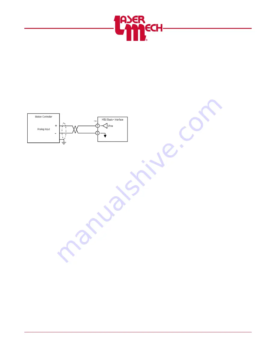
operation, the analog output from
V
HSU
should be connected to the
motion controller’s analog input. See
Figure 14
In order to achieve a maintained
distance between the sensor and
the target material, a reference must
be set. The motion control system
must be configured to accept an
offset value relating to the desired
analog sensor value.
3.4.2 V
REF
(Analog Input)
The V
ref
input is part of the equation
used to generate the V
dif
output. The
V
ref
input establishes a target
voltage level for a closed servo loop
system (i.e. a 1V input for a 1mm
standoff).
3.4.3 V
DIF
(Analog Output)
The V
DIF
output can be used as a
servo command signal when
connected to the servo drive. The
Gain factor can be set using
Basic+
HSU Utility
and has a range of +/-
50.
V
DIF
= (V
REF
- V
HSU
) x Gain
3.4.4 Ready (Digital Output)
When active, this output indicates
that the system is operating
normally. The absence of this signal
indicates a problem with the system.
It should be tied in conjunction with
the motion inhibit function of the
motion controller. If no Ready signal
is present
Verify that the sensor is
calibrated
Check the cabling
Verify that the head is not too
hot.
This output must be monitored and
action taken upon each instance of
this condition.
A fault in the Ground integrity of the
HSU will also cause the Ready
signal to deactivate.
3.4.5 Touch (Digital Output)
When active, this output indicates
that the sensor tip has come into
contact with an object. This may be
the target material, process debris
or an obstruction. All of these
conditions are not necessarily faults.
This output must be monitored and
action taken under conditions where
Touch is active for a period of time.


