LM-SYM-XX-CTRL-R1
Larson Electronics, LLC
Phone: (800) 369-6671
Fax: (903) 498-3364
www.larsonelectronics.com
1
of
2
Master Control Box for Syncing LM-SYM Series Masts
3rd Gen - Class 1 Div 1 -
Sync up to (4) Masts - LCD DIsplay, (3) Buttons
Instruction Manual
Thank you for your purchase of the Larson Electronics
LM-SYM-XX-CTRL-R1
.
WARNING:
READ CAREFULLY BEFORE INSTALLING FIXTURE. RETAIN THESE INSTRUCTIONS FOR FUTURE REFERENCE.
CRITICAL SAFETY INSTRUCTIONS:
•
INSTALLATION SHOULD ONLY BE CONDUCTED BY A QUALIFIED ELECTRICIAN IN ACCORDANCE WITH NEC AND ANY
RELEVANT LOCAL BUILDING CODES.
•
RISK OF FIRE OR ELECTRIC SHOCK. FIXTURE INSTALLATION REQUIRES KNOWLEDGE OF
FIXTURE'S
ELECTRICAL
SYSTEMS. IF NOT QUALIFIED, CONTACT A QUALIFIED ELECTRICIAN.
•
BE CERTAIN ELECTRICAL POWER IS OFF BEFORE AND DURING INSTALLATION AND MAINTENANCE.
•
MAKE SURE THE SUPPLY VOLTAGE IS THE SAME AS THE
FIXTURE'S
RATED VOLTAGE.
•
TO PREVENT WIRING DAMAGE OR ABRASION, DO NOT EXPOSE WIRING TO EDGES OF SHEET METAL OR SHARP
OBJECTS. SUITABLE FOR DAMP LOCATIONS.
The Larson Electronics LM-SYM-XX-CTRL-R1 Master Control Box provides a safe and effective way for operators to sync LM-SYM
series masts. Suitable for syncing up to 4 LM-SYM series electric winch masts, the unit facilitates start, stop and emergency stop
functions.
WIRING
Standard pigtail(flying leads) wiring
We strongly encourage a licensed electrician install this product
, in all locations especially in outdoor areas
where weatherproofing may be required. Universal voltage driver permits operation at 100V - 277V AC, 50 or 60Hz
except those factory ordered with low voltage 11V to 25V AC/DC.
Warning:
Check product label for correct input voltage!
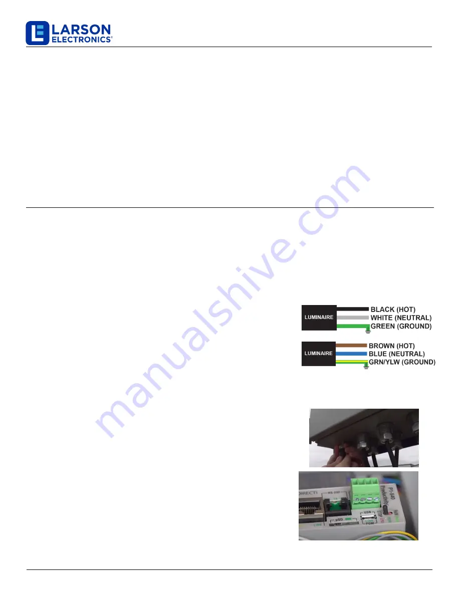
Attach supply line wires to the appropriate light fixture wires as shown
in the diagram
Secure each pair of wires according to the diagram. Utilize a junction box or
similar device and take precautionary steps for weatherproofing all
connections if installed in a location where water may come in contact with the
unit. Ensure the unit is properly grounded and that wiring is done according to
all local and national electrical/building codes.
MOUNTING
This unit is intended to be surface mounted to desired location.
OPERATION
•
Ensure sync cables are plugged in to desired towers and towers are connected
to a power source.
•
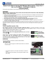
For single tower operation, put the switch inside the Master Control Box to
"STOP".
•
For synchronized tower operation, put the switch inside the Master Control
Box to "RUN".


