background image

LT-3100S GMDSS User & Installation Manual Rev. 1.02 

Installation and Mounting 

Lars Thrane A/S 

www.thrane.eu 

Page 6 of 71 

Installation and Mounting


LT-3110S Control Unit


The LT-3110S Control Unit is the master unit in the system, supporting all external interfaces and the 
operational user interface. The LT-3110S Control Unit is designed for indoor mounting. See the 
specifications in 

App. B - Specifications

 on page 58. 

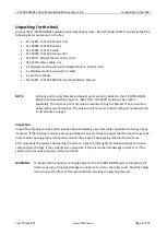
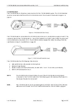
The LT-3110S Control Unit has the following interfaces: 


4-

pin power connector (male), marked ‘PWR’


Chassis ground connector, marked ‘GNDC’


N connector (female) for coaxial cable to the LT-

3130 Antenna Unit, marked ‘ANT’


Ethernet (RJ-

45) connector, marked ‘LAN’


10-

pin auxiliary connector (male), marked ‘AUX’


SIM card, marked ‘SIM’


5-pin connector (female) for LT-3120 Handset (front of the control unit) 


Figure 2: LT-3110S Control Unit (front view). 


Содержание iridium LT-3100S

Страница 1: ...User Installation Manual LT 3100S GMDSS Satellite Communications System Document Number 95 101817 Rev 1 02 Release date January 8 2020 Copyright Lars Thrane A S Denmark ALL RIGHTS RESERVED...

Страница 2: ......

Страница 3: ...Lars Thrane A S is not responsible for the content or accuracy of any translations or reproductions in whole or in part of this manual from any other source Copyright 2019 Lars Thrane A S All rights...

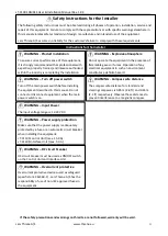
Страница 4: ...and intended use of the equipment Lars Thrane A S assumes no liability for the customer s failure to comply with these requirements Instructions for the Installer WARNING Turn off power switch Turn of...

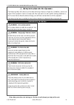
Страница 5: ...ve product enclosure Do not service the equipment with the communication cable connected Always disconnect and discharge unit cable and circuits before touching them WARNING Permanent watch In case of...

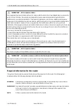
Страница 6: ...no guarantee that interference will not occur in a particular installation If this equipment does cause harmful interference to radio or television reception which can be determined by turning the equ...

Страница 7: ...stem The manual is primarily intended for installers and service personnel Personnel installing or servicing the system should be professionals with technical expertise properly trained and likewise a...

Страница 8: ...nstallation Manual Rev 1 02 Lars Thrane A S www thrane eu vi Software versions This manual is applicable to the following software Software Versions Description Version LT 3100S GMDSS System 1 01 Tabl...

Страница 9: ...Lars Thrane A S www thrane eu vii Record of Revisions Rev Description Release Date Initials 1 00 Original document November 4 2019 PT 1 01 GMDSS user functions November 19 2019 KK PT 1 02 Added FCC co...

Страница 10: ...LT 3120 Handset 9 LT 3121 Cradle 10 LT 3130 Antenna Unit 11 LT 3140S Interface Unit 15 LT 3150S Alarm Panel 16 LT 3160S Printer Adapter 18 Bracket Mount Antenna Unit 19 Pole Mount Antenna Unit 21 Int...

Страница 11: ...58 App C Outline Drawing LT 3110S Control Unit 60 App D Outline Drawing Bracket Mount Control Unit 61 App E Outline Drawing Flush Mount Control Unit 62 App F Outline Drawing LT 3130 Antenna Unit 63 Ap...

Страница 12: ...global coverage provided by the Iridium Communications Network The LT 3100S GMDSS system offers the following Iridium GMDSS services Distress Alert Safety Voice Maritime Safety Information MSI The LT...

Страница 13: ...must only be mounted using the bracket or pole mounted delivered by Lars Thrane A S The antenna unit mounts are listed with part numbers P N in Accessories on page 3 Inspection Inspect the shipping ca...

Страница 14: ...nector parts are not part of the basic system and must be ordered separately 91 100768 Aux Cable 3m 91 101183 Coaxial cable 4 9mm 10m 91 101184 Coaxial cable 4 9mm 25m 91 101137 Coaxial Cable 10 3mm 1...

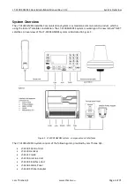
Страница 15: ...lite constellation The LT 3100S GMDSS system is working on the new Iridium NEXT satellites An overview of the LT 3100S GMDSS system is illustrated in Figure 1 The LT 3100S GMDSS system consists of the...

Страница 16: ...S GMDSS system will be released to customers with the initial software version 1 01 Software version 1 01 includes support for all GMDSS services Additional none GMDSS services might be added in later...

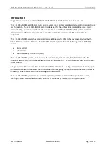
Страница 17: ...ol Unit is designed for indoor mounting See the specifications in App B Specifications on page 58 The LT 3110S Control Unit has the following interfaces 4 pin power connector male marked PWR Chassis g...

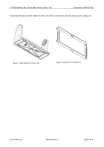
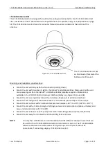
Страница 18: ...in Figure 4 and Figure 5 The Flush Mount Control Unit is not included in the LT 3100S GMDSS Satellite Communications System Basic P N 90 102071 and must be ordered separately Mounting and installatio...

Страница 19: ...02 Installation and Mounting Lars Thrane A S www thrane eu Page 8 of 71 The Bracket Mount and Flush Mount for the LT 3110S Control Unit are illustrated in Figure 4 and Figure 5 Figure 4 Bracket Mount...

Страница 20: ...0 Handset is designed for indoor mounting Check the specifications in App B Specifications on page 58 The LT 3120 Handset has the following characteristics High performance audio speaker and microphon...

Страница 21: ...LT 3120 Handset The LT 3121 Cradle specifications are available in App B Specifications on page 58 IMPORTANT The LT 3121 Cradle contains a magnet to hold on to the LT 3120 Handset Make sure that other...

Страница 22: ...isplay see Figure 35 on page 36 Mount the unit on a rigid structure with a minimum of exposure to vibration and shock Mount the unit using either the Bracket Mount or Pole Mount provided by Lars Thran...

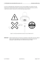
Страница 23: ...e coaxial cable N connector male to the antenna unit The coaxial cable N connector thread nut must be fastened only by using handcraft IMPORTANT Maximum allowed torque is 2 Nm when connecting the coax...

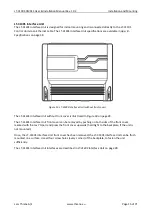
Страница 24: ...s in the order of 20 degrees To avoid near field antenna coupling a minimum distance of 2 5 m 6 ft between the radar antenna and the LT 3130 Antenna Unit must be obeyed Figure 12 is illustrating how t...

Страница 25: ...minor obstructions such as a mast will not degrade the antenna performance severely if a separation distance larger than 15 times the diameter of the obstruction is kept The LT 3130 Antenna Unit must...

Страница 26: ...cover is illustrated in Figure 30 on page 28 The LT 3140S Interface Unit front cover can be removed by pushing on both sides of the front cover marked with the text Open and press the front cover upwa...

Страница 27: ...nel consist of the following human interface functions DISTRESS button DIM button and speaker The LT 3150S Alarm Panel is delivered with a 25m cable attached to the unit The wire designation of the LT...

Страница 28: ...elivered together with the LT 3150S Alarm Panel The LT 3150S Alarm Panel with the bracket mount is illustrated in Figure 17 The LT 3150S Alarm Panel can be released from the bracket mount by using a r...

Страница 29: ...connector The LT 3160S Printer Adapter is delivered with a 25m cable attached to the unit The wire designation of the LT 3160S Printer Adapter is described in Table 3 The LT 3160S Printer Adapter can...

Страница 30: ...n the coaxial cable to the LT 3130 Antenna Unit N connector 4 Apply self volcanic tape on the N connector and cable to protect against saltwater and corrosion NOTE Always fasten the Bracket Mount Ante...

Страница 31: ...t 1 5 to 2 5 tube Antenna Unit can support tubes in the interval 1 5 to 2 5 The torques are specified in Figure 17 The bracket mount V bolts and nuts are all made of A4 stainless steel Figure 23 Brack...

Страница 32: ...protect against saltwater and corrosion 4 Screw the pole mount clockwise on the LT 3130 Antenna Unit and fasten the antenna lock pinot screw as illustrated in Figure 27 max torque 1 2 Nm 5 The LT 313...

Страница 33: ...ole Mount 1 5 tube Antenna Unit only support a 1 5 tube The pinot screws antenna and pole lock torques are specified in Figure 26 and Figure 27 The pole mount is made of milled aluminum anodized The p...

Страница 34: ...card to be operated with the Iridium satellite services The Iridium GMDSS SIM card must be bought from one of the official Iridium GMDSS Service Providers A list of Iridium GMDSS Service Providers can...

Страница 35: ...t vessel details e g Vessel name IMO number Call sign MMSI number This essential data must be delivered correctly to the Iridium GMDSS Service Provider and will be validated upon completing the LT 310...

Страница 36: ...ly negotiate an IPv4 Link Local address The current IP address can be found in the user interface display Menu System Network IP Address Auxiliary The auxiliary connector is a 10 pin connector male mo...

Страница 37: ...um length of the coaxial cable It is important to note that the input voltage of the control unit is important for the length of the coaxial cable that can be used The following formula can be used to...

Страница 38: ...voltage by 10 10 8 VDC and 21 6 VDC to compensate for variation in the power source The total DC resistance for the two cables are IMPORTANT If using a coaxial cable that is different to what is speci...

Страница 39: ...the LT 3140S Interface Unit The LT 3140S Interface Unit has the following interfaces available 4 x Ethernet 2 x RS 422 4 x GPIO 4 x CAN DC input Chassis ground The LT 3140S Interface Unit is required...

Страница 40: ...sed on 12 VDC and 24 VDC power buses nominal External DC power to the LT 3140S Interface Unit is provided by connecting a DC cable plus minus incl crimp tubes to the DC input power connector The power...

Страница 41: ...sible as soon as a Distress Alert has been activated from the DISTRESS button Off hook button The button is illustrated with a green colored handset The function of the off hook button is to activate...

Страница 42: ...In text mode the key is used to change between capital and lowercase letters Display The display contains three sections as illustrated in Figure 32 Status bar view area and soft keys The essential sy...

Страница 43: ...ellite signal and is not registered on the Iridium Network The LT 3100 system has satellite signal 0 and is registered on the Iridium Network The LT 3100 system has satellite signal 1 and registered o...

Страница 44: ...er or numeric number The numeric keypad can be used to enter text The first letter of a sentence will be in upper case The numeric keypad can be used to enter text All letters will be in lower case Th...

Страница 45: ...out as illustrated in Figure 34 The main menu is represented by four sub menus GMDSS Phone Settings and System The four sub menus are listed in Table 15 on page 35 Figure 34 LT 3110S Control Unit UI d...

Страница 46: ...C Messages Position Setup Distress Alert Setup SES Information System Test Phone Contacts Messages Call History Data History Phone Usage Settings Audio Display Date Time System Phone Setup Network Blu...

Страница 47: ...he Iridium Network and ready to use The LT 3100S GMDSS system will provide user information in the status bar and status text e g Registered showed below the Iridium connected logo The signal strength...

Страница 48: ...coaxial cable connections specifications and details in LT 3130 Antenna on page 26 Not ready Handset not connected The LT 3120 Handset is not connected to the LT 3110S Control Unit Phone calls cannot...

Страница 49: ...check the status of the Distress Alert by verifying the display information of the LT 3110S Control Unit where more information will be available The Distress Alert function will preempt any other ong...

Страница 50: ...elect the RCC to which you wish to place a priority call 2 Press the soft key Priority Call press the green off hook button or off hook the handset to open the priority dialog 3 Select a priority 4 Pl...

Страница 51: ...T 3100S GMDSS system is ready for making a voice call Check that the system status system text and icons as described in System on page 36 shows the correct system information Dialing a mobile origina...

Страница 52: ...Rev 1 02 Using the system Lars Thrane A S www thrane eu Page 41 of 71 a Lift the handset out of the cradle or b Press the off hook button green handset button 3 The LT 3100S GMDSS system will now esta...

Страница 53: ...tep by step 1 Lift the handset out of the cradle or press the off hook button green handset button 2 Confirm that a ready tone is available in the handset or in the control unit speaker 3 Please enter...

Страница 54: ...successfully connected where MM are minutes and SS are seconds The Connecting and Duration MM SS states are illustrated in Figure 38 and Figure 39 Non priority messaging Non priority messages are sen...

Страница 55: ...SOG are optional and can be set to zero if unknown 6 When all fields have been assigned a value press Apply soft key to apply the manual position NOTE The manual position should be updated minimum eve...

Страница 56: ...s its severity The BAM concept defines 4 priorities Emergency Alarm Alarm Warning and Caution The LT 3100S GMSDS system can raise alerts of the following priorities Warning Condition requiring immedia...

Страница 57: ...udible signal Warning Active unacknowledged Alert condition present Alert not acknowledged Yes Active silenced Alert condition present Alert not acknowledged but audible signal has been silenced by th...

Страница 58: ...that the number of individual alerts obscures the display of equally important additional alerts for example due to the active alert list length exceeding the maximum display capability of the alert s...

Страница 59: ...has additional knowledge regarding an alert situation which caused the LT 3100S GMDSS system to raise an alert the CAM system may apply responsibility transfer and apply revaluation by raising a new...

Страница 60: ...either directly by connecting an Ethernet cable between a PC and the LT 3110S Control Unit or by connecting the LT 3110S Control Unit to a Local Area Network LAN to where the PC is connected NOTE The...

Страница 61: ...ne SOLAS vessel Data SIP Tracking GNSS and NMEA output Reset The functionality of the Dashboard Software update and Diagnostic report web pages are described in further details in this version of the...

Страница 62: ...l be available on the official company website www thrane eu under the specific product Finally click the Upload button to start the upload of the new software image The upload and installation of the...

Страница 63: ...s The IP address is valid if the Link Status is showing Up The IP address is assigned dynamically by a DHCP server in default configuration 3 From the PC start a browser e g Microsoft Edge Explorer or...

Страница 64: ...unit serial numbers identified The unit part numbers and the unit serial numbers are identified on the unit label which is found on the backside or at the bottom side of the units Alternatively use t...

Страница 65: ...one of the two modes at any given time Alerts of the disabled mode will be cleared Printing Yes Responsible for printing GMDSS messages If user disables printing any raised printing related alerts wi...

Страница 66: ...is lost and stay lost for a minimum of 10 minutes Rectified if GNSS receiver obtains a valid position Cleared to normal if position mode is set to manual ID 3079 Priority Caution Category B Title Pap...

Страница 67: ...le Urgency Rx Normal w o acknowledge Yes Description Incoming urgency warning Check GMDSS display What to do Read the received urgency MSI message or urgency priority message see Maritime Safety Infor...

Страница 68: ...hen the unknown SIM card is removed ID 3123 Priority Caution Category B Title Safety Rx Description Check new received safety message What to do Read the received priority message see Priority messagi...

Страница 69: ...ional 15 C to 55 C 5 F to 131 F IP rating dust and water IP 30 Interfaces Ethernet auxiliary DC input chassis ground Antenna Unit N conn handset Bluetooth SIM card Input voltage BT transmitter Max RF...

Страница 70: ...terfaces 4 x Ethernet 2 x RS 422 4 x GPIO 4 x CAN DC input chassis ground Input voltage 10 24 VDC LT 3150S Alarm Panel Weight Weight incl 25m cable 0 07 kg 0 15 lbs 1 29 2 84 lbs Dimensions 52 0 x 82...

Страница 71: ...LT 3100S GMDSS User Installation Manual Rev 1 02 Appendixes Lars Thrane A S www thrane eu Page 60 of 71 App C Outline Drawing LT 3110S Control Unit Figure 45 Outline Drawing LT 3110S Control Unit...

Страница 72: ...3100S GMDSS User Installation Manual Rev 1 02 Appendixes Lars Thrane A S www thrane eu Page 61 of 71 App D Outline Drawing Bracket Mount Control Unit Figure 46 Outline Drawing Bracket Mount Control Un...

Страница 73: ...T 3100S GMDSS User Installation Manual Rev 1 02 Appendixes Lars Thrane A S www thrane eu Page 62 of 71 App E Outline Drawing Flush Mount Control Unit Figure 47 Outline Drawing Flush Mount Control Unit...

Страница 74: ...LT 3100S GMDSS User Installation Manual Rev 1 02 Appendixes Lars Thrane A S www thrane eu Page 63 of 71 App F Outline Drawing LT 3130 Antenna Unit Figure 48 Outline Drawing LT 3130 Antenna Unit...

Страница 75: ...LT 3100S GMDSS User Installation Manual Rev 1 02 Appendixes Lars Thrane A S www thrane eu Page 64 of 71 App G Outline Drawing LT 3140S Interface Unit Figure 49 Outline Drawing LT 3140S Interface Unit...

Страница 76: ...LT 3100S GMDSS User Installation Manual Rev 1 02 Appendixes Lars Thrane A S www thrane eu Page 65 of 71 App H Outline Drawing LT 3150S Alarm Panel Figure 50 Outline Drawing LT 3150S Alarm Panel...

Страница 77: ...T 3100S GMDSS User Installation Manual Rev 1 02 Appendixes Lars Thrane A S www thrane eu Page 66 of 71 App I Outline Drawing LT 3160S Printer Adapter Figure 51 Outline Drawing LT 3160S Printer Adapter...

Страница 78: ...eu Page 67 of 71 App J Outline Drawing Pole Mount Antenna Unit NOTE The Pole Mount 1 5 tube Antenna Unit interfaces to a tube of maximum 1 5 38 1 mm measured outer diameter The total weight of the Pol...

Страница 79: ...71 App K Outline Drawing Bracket Mount Antenna Unit NOTE The Bracket Mount 1 5 to 2 5 tube Antenna Unit interfaces to a tube of maximum 2 5 63 5 mm measured outer diameter The total weight of the Bra...

Страница 80: ...LT 3100S GMDSS User Installation Manual Rev 1 02 Appendixes Lars Thrane A S www thrane eu Page 69 of 71 App L Outline Drawing LT 3120 Handset Figure 54 Outline Drawing LT 3120 Handset...

Страница 81: ...LT 3100S GMDSS User Installation Manual Rev 1 02 Appendixes Lars Thrane A S www thrane eu Page 70 of 71 App M Outline Drawing LT 3121 Cradle Figure 55 Outline Drawing LT 3121 Cradle...

Страница 82: ...LT 3100S GMDSS User Installation Manual Rev 1 02 Appendixes Lars Thrane A S www thrane eu Page 71 of 71 App N EU Declaration of Conformity Not available yet pending BABT approval...

Страница 83: ...Lars Thrane A S Skovlytoften 33 2840 Holte Denmark www thrane eu...

Отзывы: