background image


ASSEMBLY INSTRUCTIONS 


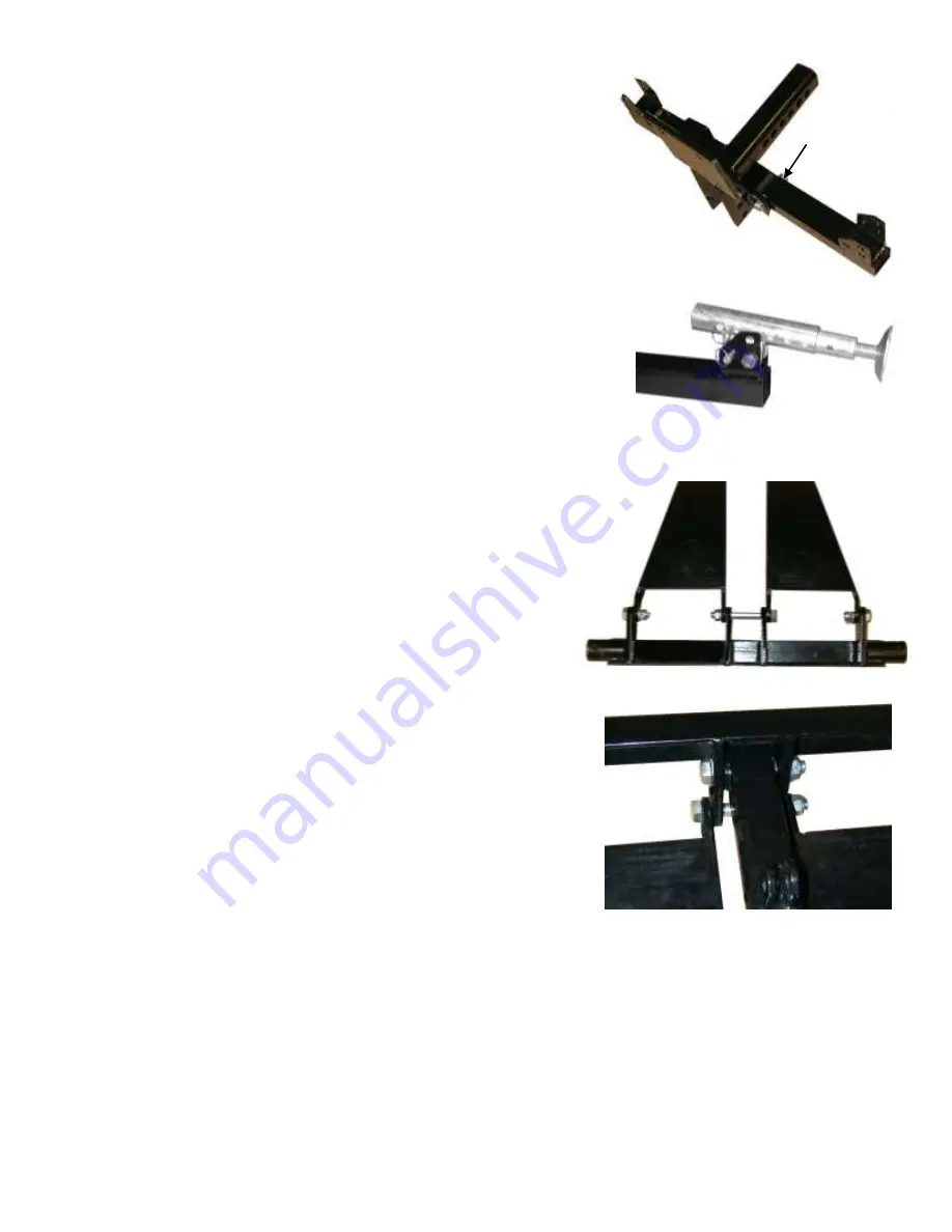
1 Attach the Outrigger Arm 

     Attach outrigger support (F) to the hitch adapter (A) using two M12 x 75 bolts (#14)                    A                 F 
with M12 flat washers (#5) and M12 nylon lock nuts (#4).   
 

2 Attach the Outriggers 

Attach the two outrigger assemblies to the far outside lower holes in the outrigger 
tube (F) as shown. Use a M12 x 75 bolt (#14) with a M12 washer (#5) and M12   
nylon lock-nut (#4) on each bolt. Position the outrigger tubes as shown, then install a  
quick release pin through the  outrigger tube and outrigger assembly as shown.  
After installing the pin, replace the securing clip in the pins.                                                                                                                    


The assembly should now look like this……. 


3 Attach the Guide Arms to the Pivot Tube 

     Attach the Guide Arms to the Pivot Tube. Start at the center holes (A) and  
Use an M12 x 105 (#11) bolt with an M12 washer (#5) and an M12 nylon                  B                    A                                B          
lock-nut (#4). Then Use M12 x 35 bolts (#6) with M12 washers (#5) and  
M12 nylon lock-nuts (#4) on each of the Outside holes (B). 


 D 

4 Attach the Lifting Arm to the Pivot Tube 

     Attach the Lifting Arm (B) to the Pivot Tube (D) using an M12 x 85 bolt (#7) and  
An M12 washer (#5) and an M12 nylon lock-nut(#4). Notice that the tabs with the holes 
In them face up and are closest to the Pivot Tube. 


B


5 Attach the Lifting Arm and Guide Arms to the Hitch Adapter Plate 

     Attach the Lifting Arm (B) to the Hitch Adapter Plate (A) using an M12 x 85 bolt (#7)                                                        

and an M12 washer (#5) and an M12 h all the parts. Secure it with an M12 
washer (#5) and an M12 nut (#4). nylon lock-nut (#4). Now attach the two ends of the  
Guide Arms (C) using an M12 x 105 bolt (#11) throug 


Содержание TGL-500

Страница 1: ...1 OWNER S MANUAL MODEL TGL 500 HITCH LIFT For Customer Service Call or Fax 1 800 87 LARIN ...

Страница 2: ... quick release pins and stabilizer clamp outrigger assembly outriggers wrench and deck tie downs Motorized cable module CTN 2 This box contains the motorized cable module hex head cap screws washers and nylon lock nuts required to mount the module along with a hex key allen wrench for these bolts and cable set for connection to the battery Motor Controls CTN 3 This box contains the Pistol Grip Tri...

Страница 3: ...d be aware that repair of this equipment requires specialized knowledge and facilities It is recommended that an annual inspection be made by the manufacturer s authorized repair facility and that any defective parts decals or safety labels or signs be replaced with the manufacturer s specified parts If you encounter any problems or difficulties contact the manufacturer s toll free at 1 800 87 LAR...

Страница 4: ... Pivot Tube Attach the Guide Arms to the Pivot Tube Start at the center holes A and Use an M12 x 105 11 bolt with an M12 washer 5 and an M12 nylon B A B lock nut 4 Then Use M12 x 35 bolts 6 with M12 washers 5 and M12 nylon lock nuts 4 on each of the Outside holes B D 4 Attach the Lifting Arm to the Pivot Tube Attach the Lifting Arm B to the Pivot Tube D using an M12 x 85 bolt 7 and An M12 washer 5...

Страница 5: ... into the upright position While the helper holds the Deck Plate up install an M10 washer 3 and an M10 nylon lock nut 2 onto each of the M10 bolts 1 Install the two quick release pins and clips in the deck plate Notice that there is a place to mount your license plate on the bottom of the Deck Plate if needed The assembly should now look like this 9 Install the Motorized Cable Module to the Hitch ...

Страница 6: ...witch is adjusted at the time of installation to the truck The Limit Switch viewed from the other side It is now time to install the unit to your truck Having an assistant available will make the next step easier INSTALLATION INSTRUCTIONS 11 Install the Lift to the Truck With the help of your assistant install the Hitch Adapter Plate tube into The receiver tube of your hitch Install a hitch pin no...

Страница 7: ...p trigger has a yellow lever above the trigger This lever controls the direction of the Hitch Lift Observe the drum of the Cable Module while you depress the pistol grip trigger You will need to release cable from the drum in order to connect it to the Lifting Arm B When you are sure that the cable drum will rotate in the direction to pay out cable depress the trigger while pulling on the end of t...

Страница 8: ...ld be aware that repair of this equipment requires specialized knowledge and facilities It is recommended that an annual inspection be made by the manufacturer s authorized repair facility and that any defective parts decals or safety labels or signs be replaced with the manufacturer s specified parts If you encounter any problems or difficulties contact the manufacturer s toll free at 1 800 87 LA...

Страница 9: ...ove the ground 14 Remove the retaining clips and pull the quick release pins from the Deck Plate The Deck Plate will be free to rotate after the pins are pulled make sure that you are not in a position to be struck by the Deck Plate 15 Rotate the Deck Plate up to the storage position and replace the pins and clips 16 Move the direction switch to the UP position 17 Press the trigger switch to raise...

Страница 10: ...straps Carefully transfer the load to ground 14 Raise the tailgate 15 Change the direction switch to UP 16 Operate the trigger to raise the Deck Plate until it is about 2 inches above the ground 17 Remove the retaining clips and pull the quick release pins from the Deck Plate The Deck Plate will be free to rotate after the pins are pulled make sure that you are not in a position to be struck by th...

Страница 11: ...is recommended that an annual inspection be made by the manufacturer s authorized repair facility and that any defective parts decals or safety labels or signs be replaced with manufacturer s specified parts If you encounter any problems or difficulties contact the manufacturer toll free at 1 800 87 LARIN Ask for customer service DAMAGED PRODUCT Any lift that appears to be damaged in any way or op...

Страница 12: ...w the exclusion of consequential damages so the foregoing exclusions may not apply to you For warranty service please return the product prepaid to Larin Corporation 2029 Business Parkway Ontario California 91761 Be certain to include your name and address proof of purchase date and description of the problem and the repaired or replaced product will be sent to you freight collect RETURN POLICY DO...

Отзывы: