ML62Q1577 Reference Board User’s Manual
FEBL62Q1577RB
12
Страница 1: ...FEBL62Q1577RB 01 ML62Q1577 Reference Board User s Manual Issue Date January 19 2018 ...
Страница 2: ...re not designed to be radiation tolerant 7 For use of our Products in applications requiring a high degree of reliability as exemplified below please contact and consult with a LAPIS Semiconductor representative transportation equipment i e cars ships trains primary communication equipment traffic lights fire crime prevention safety equipment medical systems servers solar cells and power transmiss...
Страница 3: ... Reference Board 3 2 1 Power Circuit 3 2 2 Connector for EASE1000 CNE 4 2 3 LED P20 P21 P22 5 2 4 XT0 PIO0 XT1 PIO1 5 2 5 P75 P74 P73 P72 P71 6 3 User Interface 7 4 Precaution for use 8 5 PCB specification BOM and Schematic 9 5 1 ML62Q1577 Reference Board PCB specification 9 5 2 ML62Q1577 Reference Board BOM 11 5 3 ML62Q1577 Reference Board Schematic 11 Revision History 13 ...
Страница 4: ...his manual describes about the ML62Q1577 Reference Board RB D62Q1577TB100 Refer to following documents when necessary ML62Q1500 Group User s Manual Describes about the microcontroller ML62Q1500 Group EASE1000 User s Manual Describes about the On chip emulator EASE1000 ...
Страница 5: ...ware specification of ML62Q1577 Reference Board is indicated to Table 1 Table 1 ML62Q1577 Reference Board Hardware specifications Mounted LSI U1 ML62Q1577 100pin TQFP Other Mounted components PWR Jumper for selecting the power supply input 3pin pin header and short pin J1 Jumper for selecting RESET_N pin 3pin pin header and short pin J2 Jumper for selecting P00 TEST0 pin 3pin pin header and short ...
Страница 6: ...ce Board User s Manual FEBL62Q1577RB 2 1 2 ML62Q1577 Reference Board Outline Drawing Fig 1 show the ML62Q1577 Reference Board Fig 1 ML62Q1577 Reference Board Outline Drawing LED P20 P21 P22 CN1 CN2 CNE Jumper PWR J2 J1 ...
Страница 7: ...rocedure in case of setting PWR jumper to the USR side and using EASE1000 The procedure of power supply ON 1 The USB cable of EASE1000 is connected 2 The power supply of user target system is turned on The procedure of power supply OFF 1 The power supply of user target system is turned off 2 The USB cable of EASE1000 is removed CNE ML62Q1577 VDD VSS 1uF VDD C PWR USR CNE VTref 3 3VOUT VSS 1 13 2 4...
Страница 8: ...1000 Interface Note P00 TEST0 pin P00 TEST0 pin of ML62Q1577 is initially set as the pulled up input mode When using EASE1000 do not set it as an output mode by the application program otherwise EASE1000 cannot communicate with the ML62Q1577 CNE ML62Q1577 RESET_N P00 TEST0 10k VDD C J1 USR CNE RST_OUT SCK SDATA 5 7 CN1 RESET_N P00 TEST0 6 7 J2 C USR CNE ...
Страница 9: ... LEDs through jumper chip Remove the jumper chip when not using the LEDs Fig 4 Jumper chip removal of LEDs 2 4 XT0 PIO0 XT1 PIO1 ML62Q1577 Reference Borad can mount cylinder type or SMD type crystal oscillator Fig 5 Example of processing of Crystal Oscillator Remove when not using the LEDs Cylinder type Crystal Oscillator Capacitors Capacitors SMD type Cristal Oscillator ...
Страница 10: ...connected with CN1 using jumper chip ML62Q1577 Reference Board can not use C5 C6 C7 and C8 Therefore please do not mount various parts on C5 C6 C7 and C8 Fig 6 P75 P71 Circuit C5 C6 C7 C8 Do not mount parts CN1 ML62Q1577 P75 P71 Jumper Chip C8 P74 P73 P72 C7 C6 C5 J8 J9 J10 J11 J12 24 25 26 27 28 ...
Страница 11: ...PB4 6 RESET_N 31 P05 6 P55 31 PB5 7 P00 TEST0 32 P06 7 P14 32 P40 8 P01 33 P07 8 P15 33 P41 9 P80 34 P10 9 P16 34 P30 10 P81 35 P11 10 P17 35 P31 11 P82 36 P12 11 P20 36 P32 12 P83 37 P13 12 P21 37 P33 13 P84 38 P50 13 P22 38 P60 14 P85 39 P51 14 P23 39 P61 15 P86 40 P52 15 P24 40 P62 16 P87 41 P53 16 P25 41 P63 17 P44 42 P90 17 P26 42 P64 18 P45 43 P91 18 P27 43 P65 19 P02 44 P92 19 P56 44 P66 20...
Страница 12: ...without notice confirm the content is the latest when using the board 3 See another documents ML62Q1500 group user s manual and EASE1000 user s manual when using the ML62Q1577 Reference Board 4 Confirm the final electrical characteristics by using the mass production parts on your mass production boards 5 LAPIS support replacing the board for an initial failure soon after the shipment can not supp...
Страница 13: ...2Q1577RB 9 5 PCB specification BOM and Schematic 5 1 ML62Q1577 Reference Board PCB specification Fig 7 shows the Reference Board PCB dimensional outline drawing and layout of components PCB part number RB D62Q1577TB100 Dimension 55 88mm x 93 98mm ...
Страница 14: ...ML62Q1577 Reference Board User s Manual FEBL62Q1577RB 10 Fig 7 Reference Board PCB dimensional outline drawing and layout of components Top view ...
Страница 15: ...ROHM 8 SML 210PT P20 P21 P22 LED Green 2012 2 0x1 2mm 3 ROHM 9 MCR03EZPJ271 R1 R2 R3 Resistor 270Ω 1608 1 6x0 8mm 3 ROHM 11 MCR03EZPJ103 R4 Resistor 10kΩ 1608 1 6x0 8mm 1 ROHM 12 VT 200 F 12 5pF X1 X tal 32 768kHz 12 5pF 2PIN 1 SII 13 HIF3GA 2 54SP Short pin 3 HIROSE 14 FF013 AR79 Rubber leg 4 KOYO FASTENER 15 P3555 Push rivet 4 KOYO FASTENER 16 C5 C6 C7 C8 Unmounted 1608 1 6x0 8mm 3 17 CN1 CN2 Un...
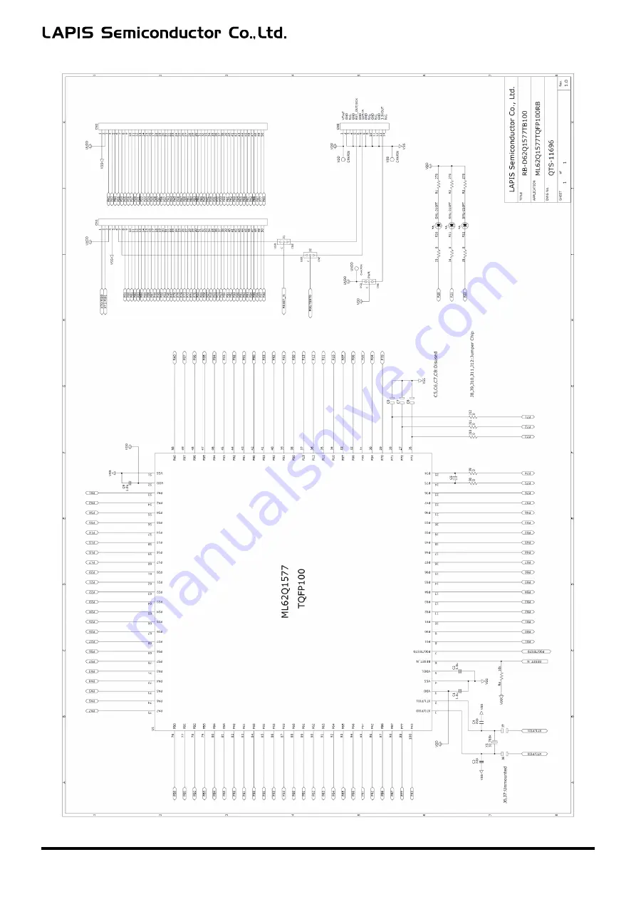
Страница 16: ...ML62Q1577 Reference Board User s Manual FEBL62Q1577RB 12 ...
Страница 17: ...ML62Q1577 Reference Board User s Manual FEBL62Q1577RB 13 Revision History Document No Issue Date Page Description Previous Edition New Edition FEBL62Q1577RB 01 January 19 2018 First edition ...