5
f e a t u r e s a n d s p e c i f i c a t i o n s
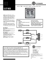
1. F/R INPUT SWITCH
2. FRONT & REAR CHANNEL MID CUT Q
SELECTORS
3. FRONT & REAR CHANNEL MID CUT
CONTROLS
4. Front & Rear Channel High-Pass
Phase Inverters
5. Front Frequency & Gain Controls
6. Rear Frequency & Gain Controls
7. Subwoofer Frequency & Gain Controls
8. Subwoofer Phase Inverter &
Stereo/Mono Switches
9. Bass Boost Level & Frequency
Controls
10. Front Channel Output Terminals
In the “2CH” position, rear inputs are split and directed to the front and rear channels simultaneously. This feature should be used when the head unit
has only one pair of output jacks.If the source unit has independent front and rear channel outputs, disengage the parallel input by sliding the switch to
the “4CH” position.
The Q slide switches select Q values of 1, 3 or 6 on the 180Hz Mid Cut filters. The maximum amount of cut possible (at 180Hz) with the Mid Cut Controls
increases with Q value : at Q=1, cut is -10dB; at Q=3, cut is -13dB; and at Q=6, cut is -17dB, Lanzar suggests that for the wider gentler attenuation which
is effective in larger vehicles, one should use a low Q value, which affects a wider band of frequencies. In smaller vehicles, setting a higher Q value is
usually preferable, which affecting a narrower band of frequencies.
For best results, you may wish to use the Mid Cut controls and Q Selectors in conjunction with the PHASE switches, in different combinations.
These controls is permit the frequencies around 180 Hz to be attenuated or cut the amount set by the Q selector. In the 180 Hz frequency range, by a
maximum of 10dB. In this frequency range many automobile sound systems require attenuation, due to the acoustic peak that exists in the acoustical
frequency response of typical vehicles. This acoustical peak in response is usually a result of the relatively small interior listening volume of an automobile,
as well as the listener's close proximity to the bass speakers.
Positioning the switch to “180” position shifts the signal 180˚ out of phase relative to the front and rear output signals.
There are 3 frequency controls for the front channels. Mid High Pass Control sets the low crossover point for the midrange drivers, between 40Hz and
240Hz. Mid Low Pass Control locates the high crossover point for the midrange drivers between 1.6kHz and 8kHz. High Pass Control sets the low crossover
point for the high frequency drivers between 1.6kHz and 8kHz. There are Front Gain Controls for both the midrange drivers and the high frequency drivers.
There are 3 frequency controls for the rear channels. Mid High Pass Control sets the low crossover point for the midrange drivers, between 40Hz and 240Hz.
Mid Low Pass Control locates the high crossover point for the midrange drivers between 1.6kHz and 8kHz. High Pass Control sets the low crossover point
for the high frequency drivers between 1.6kHz and 8kHz. There are Rear Gain Controls for both the midrange drivers and the high frequency drivers.
The Subwoofer Frequency Control is used to select a crossover point between 40Hz and 240HZ. At the selected frequency the bass begins to roll off a
12dB per octave. A Subwoofer Output Gain Control adjusts the output signal level for the sub channel.
Positioning the Subwoofer Phase Switch to “180” position shifts the signal 180˚ out of phase relative to the front and rear output signals. This is especially
valuable in minimizing some of the “tubbyness” that is characteristic of many vehicles. The Stereo/Mono Switch sums the signal, in the mono mode, to
provide a mono output for those users who are utilizing a single channel subwoofer design.
These controls are used to equalize the subwoofer channel. The Bass Boost Frequency Control is used for selecting a frequency between 40Hz and 120Hz.
The Bass Boost Level Control adjusts the gain from 0 to +12dB.