

SM24TBT2DPA Quick Start Guide
33736 Rev. F
Page
2
of
2
Connect to Power
:
CAUTION
! Hazardous Area: Do Not remove this cover. Trained service people only.
No serviceable components inside.
CAUTION
: Hot Surfaces.
WARNING
: For continued protection against risk of
fire, replace only with same type & rating of fuse.
Note
:
‘To Keep Warranty Please Do NOT Remove’ sticker.
Warning
: Class I Equipment. This equipment must be earthed. Power plug must be connected to a properly wired
earth ground socket outlet. An improperly wired socket outlet could place hazardous voltages on accessible
metal parts.
Warning
: Shock hazards exist that can result in serious injury or death if safety instructions are not
followed.
Note
: This product is to be connected only to UL listed PoE networks and without routing to the outside
plant.
Power Connection Warning
:
Connect power supply to switch first, then connect the power supply to
power. Otherwise catastrophic product failure may occur.
1.
Verify power is off to the DC circuit that you are
going to attach to the switch PoE DC-input connector. This can be either of two power supplies (AC or DC input)
or site source DC.
2
. Put a safety flag and lockout device at the source power circuit breaker or put a piece of tape
over circuit breaker handle to prevent accidental power restore while you work on the circuit. See the
Install
Guide
.
Power Disconnection
: After successful boot:
1.
Turn off power to switch.
2.
Disconnect cables.
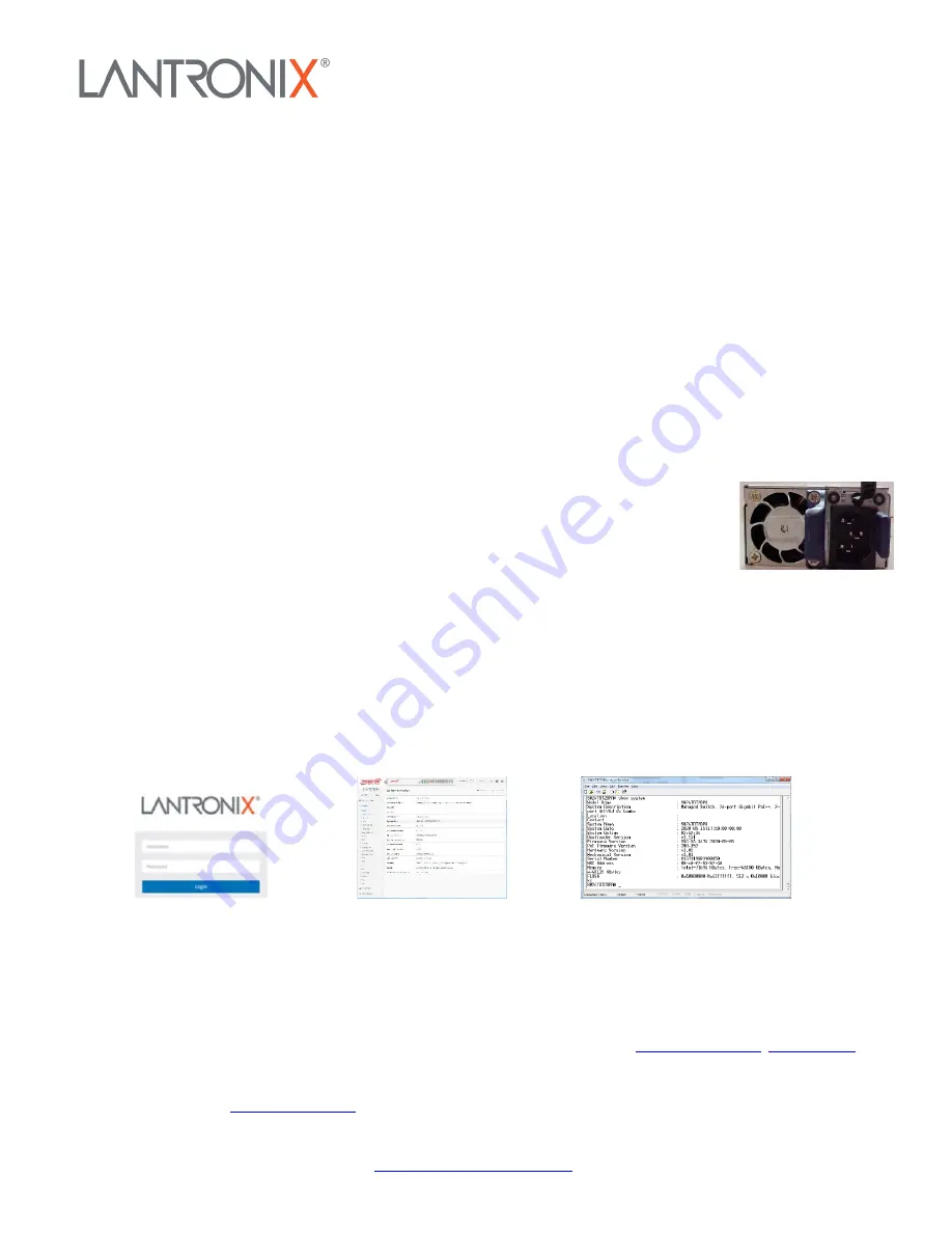
Connect AC Power Cord
:
Warning
: Risk of electrical shock.
Warning
: Shock/damage hazard exists if power
supply installed/removed with power on.
1.
See “Grounding” section above.
2.
Remove
blank faceplate or use the one open power supply slot.
3.
Fasten the AC Power Supply with
the slotted retaining screw.
4.
Insert the provided AC Power plug into the switch AC
receptacle (power inlet).
5.
Connect the other end of the AC power cord to the AC power
outlet.
6.
Check that
AC OK
and
DC OK
LEDs are lit.
Initial Config via Web Browser
:
1.
Connect PC Ethernet RJ45 connector to switch via standard Ethernet LAN
cable.
2.
Power up PC to be used for initial config.
3.
Reconfigure PC’s IP address & Subnet Mask to communicate
with switch.
4.
Power up switch to be initially configured and wait until it finishes its start-up processes.
5.
Connect PC to any port on the switch using standard Ethernet cable; make sure switch port LED is lit.
6.
In Web browser, enter switch default IP address (192.168.1.77) and Subnet Mask (255.255.255.0). The Login
page displays.
7.
Enter factory default Username (admin) and Password (admin).
8.
Click the “Login” button to log
into the switch. See the
Web User Guide
.
Initial Config via CLI
:
1.
Use an RJ-45 cable to connect a terminal or PC/terminal emulator to the switch.
2.
Attach the RJ-45 serial port on switch front panel to cable for Telnet/CLI configuration.
3.
Attach the other end of
the DB-9 cable to a PC running Telnet or a terminal emulation program.
4.
After first time switch power up,
perform initial switch config using the CLI. See the
CLI Reference
for other switch features.
Related Documentation
: SMxxTAT4Xx Install Guide 33785, Web User Guide 33786, CLI Reference 33787.
Contact Us
: Toll Free: 800-526-8766. Phone: 949-453-3990. Fax: 949-453-3995.
© 2021 Lantronix, Inc. All rights reserved. No part of the contents of this publication may be transmitted or reproduced in any form or by
any means without the written permission of Lantronix. Lantronix is a registered trademark of Lantronix, Inc. in the United States and
other countries. Patented:
; additional patents pending. All other trademarks and trade names are the property of
their respective holders.


