background image


SMxxTAT4Xx Family 

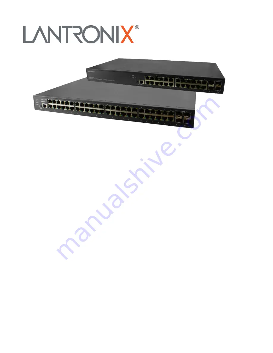
SM48TAT4XA-RP 

Managed Gigabit Ethernet PoE+ Switch 

(48) 10/100/1000Base-T Ports + (4) 1G/10GBase-X SFP+ Ports


SM24TAT4XB 

Managed Gigabit Ethernet PoE+ Switch   

(24) 10/100/1000Base-T Ports + (4) 1G/10GBase-X SFP+ Ports 

Install Guide 


Part Number 33785 

Revision F February 2023 

Содержание SM TAT4X Series

Страница 1: ...d Gigabit Ethernet PoE Switch 48 10 100 1000Base T Ports 4 1G 10GBase X SFP Ports SM24TAT4XB Managed Gigabit Ethernet PoE Switch 24 10 100 1000Base T Ports 4 1G 10GBase X SFP Ports Install Guide Part...

Страница 2: ...ce of the information provided herein Lantronix shall have no liability whatsoever to any user for any damages losses and causes of action whether in contract or in tort or otherwise in connection wit...

Страница 3: ...es so at their own risk and agrees to fully indemnify Lantronix for any damages that may result from such use or sale Attention This product like all electronic products uses semiconductors that can b...

Страница 4: ...AC Power Connector 25 Electrical Safety Warnings 26 Installation 27 Package Contents 27 Power Cord Included 27 Safety Instructions for Rack Mount Installations 27 Mounting the Switch in a 19 inch Rac...

Страница 5: ...ia CLI 36 Troubleshooting 37 Basic Troubleshooting 37 LED Troubleshooting 37 PoE Troubleshooting 38 Compliance Information 39 Declaration of Conformity 39 FCC Regulations 39 Canadian Regulations 40 Ro...

Страница 6: ...management simplicity better user experience and lowest total cost of ownership Key Features L2 Managed features provide easier manageability robust security and QoS Built in Device Management System...

Страница 7: ...roducts For ConsoleFlow cloud based software as a service select an annual subscription model CF NWSCLOUDSAAS xYR ConsoleFlow Cloud Subscription x Years where x 1 3 or 5 year subscription CF NWS ONPRE...

Страница 8: ...rature Storage Temperature Altitude Fahrenheit Centigrade Fahrenheit Centigrade Feet Meters 32 to 122 0 to 50 4 to 158 20 to 70 10000 3000 Dimensions Weights Humidity Model Dimensions WxHxD Weight Ope...

Страница 9: ...Class A EN61000 3 2 2014 EN6100 3 3 2013 EN 55024 2010 A1 2015 IEC 61000 4 2 Edition 2 0 2008 12 IEC 61000 4 3 Edition 3 2 2010 04 IEC 61000 4 4 Edition 3 0 2012 04 IEC 61000 4 5 Edition 3 0 2014 05...

Страница 10: ...to be configured for each 802 1X port on the device to provide limited services to non 802 1X compliant clients Q in Q double tag VLAN Business customers of service providers often have specific requ...

Страница 11: ...rward multicast traffic over Layer 2 network in conjunction with IGMP snooping Layer 3 Switching IPv4 Static Routing IPv4 Unicast Static routing IPv6 Static Routing IPv6 Unicast Static routing Securit...

Страница 12: ...the types of payloads contained in the packet being transmitted DSCP based Differentiated Services DiffServ Layer 3 DSCP QoS IP packets can carry either an IP precedence IPP value or a Differentiated...

Страница 13: ...and Play Forum was formed to standardize discovery and control of networked devices See the Open Connectivity Foundation webpage CDP Aware CDP operation is restricted to decoding incoming CDP frames t...

Страница 14: ...PDs Device Management System DMS Graphical Monitoring Topology view Intuitive way to configure and manage switches and devices with visual relations Floor view Easily drag and drop PoE devices to help...

Страница 15: ...g 60 minutes later 1G TP Port x 48 10G SFP x 4 110 15 09 0 98 1659 90 1626 70 Non PoE Full loading 60 minutes later 1G TP Port x 48 10G SFP x 4 110 0 93 0 94 102 30 96 16 AC 220V Input Status Operatio...

Страница 16: ...2 00 39 90 Non PoE Full loading 60 minutes later 1G TP Port x 24 10G SFP x 4 100 0 45 0 97 45 00 43 65 Note Apparent Power VA AC Voltage x AC Current Consumption Real Power W Apparent Power VA x Power...

Страница 17: ...P x 4 220 0 27 0 72 59 40 42 77 Note Apparent Power VA AC Voltage x AC Current Consumption Real Power W Apparent Power VA x Power Factor 4 AC 240V Input SM24TAT4XB Device Status Operation Interface AC...

Страница 18: ...h Lantronix is not responsible Other related manuals are listed below SMxxTAT4Xx Quick Start Guide 33784 SMxxTAT4Xx Web User Guide 33786 SMxxTAT4Xx CLI Reference 33787 API User Guide for SM24TAT4XB an...

Страница 19: ...ront panel Ports The front panel data ports are described below Console Port The front panel Console port provides an RJ 45 Console port to connect to a PC or terminal for Command Line Interface CLI c...

Страница 20: ...se LEDs to understand the port status in different modes after changing the mode by pressing the Mode Reset button Mode LED Indicates the mode of all ports on the switch You can press the Mode Reset b...

Страница 21: ...ending or receiving data 10M 100M Link Act Amber Color RJ45 Port Right LED Behavior Light off port disconnected or link failed Amber Light on Link Present No Activity Amber Blinking Activity Port is s...

Страница 22: ...cates that the switch is running normally Red Blinking N A Link Act Speed Green The Port Status LEDs are displaying link status network activity and speed of each port SYS Green Single Color Use Mode...

Страница 23: ...connected device Otherwise the port may have been disabled through the switch user interface SFP Ports Blue On The port is enabled and established a link to connected device and the connection speed...

Страница 24: ...witch to Factory Defaults To restore the original factory default settings back to the switch Note Based on the table below you can determine which task is being performed by reading the LED behaviors...

Страница 25: ...wer Connector SM24TAT4XB back panel contains the AC Power Connector AC Power Connector The back panel provides the AC Power Connector marked AC Line 100 200V 50 60Hz Note The switch is an indoor devic...

Страница 26: ...worden ge nstalleerd S curit lectrique IMPORTANT Cet quipement doit tre utilis conform ment aux instructions de s curit S hk turvallisuus T RKE T m laite on asennettava turvaohjeiden mukaisesti Sicur...

Страница 27: ...il For example SM24TAT4XB NA Safety Instructions for Rack Mount Installations The instructions below or similar are intended for rackmount installation environments 1 Elevated Operating Ambient if ins...

Страница 28: ...screwdriver to secure the brackets 2 Place the switch on a rack shelf in the rack Push it in until the oval holes in the brackets align with the mounting holes in the rack posts 3 Attach the brackets...

Страница 29: ...cally do not look into laser ports Ensure that each SFP port at which laser beams are or will be present is occupied by an SFP that is locked in position 1 Position the SFP device at either installati...

Страница 30: ...er supply to power Otherwise catastrophic product failure may occur 1 Verify that power is off to the DC circuit that you are going to attach to the switch PoE DC input connector This can be either of...

Страница 31: ...wer Cord Retainer if used 3 Pinch the Pull Bar and the Locking Lever together and pull the old Power Supply from the chassis slot 4 Carefully insert the new Power Supply into the chassis slot until th...

Страница 32: ...dundancy Dual Hot Swappable Power Supplies Unpacking Power Supply The power supply is packed separately Unpack the power supply and save the packaging for possible future use The optional second power...

Страница 33: ...e chassis until the Locking Lever clicks 3 Fasten the AC Power Supply with the Mounting Screws and Power Cord Retainer if used 4 Continue with Connecting the AC Power Cord above Note This product is t...

Страница 34: ...IEEE Std 802 3 2015 increases the maximum PD power available by utilizing all four pairs in the specified structured wiring plant This represents a substantial change to the capabilities of Ethernet...

Страница 35: ...le for a PC running Windows 7 8 x 10 is as follows 2a Type network and sharing into the Search box in the Start Menu 2b Select Network and Sharing Center 2c Click on Change adapter settings on the lef...

Страница 36: ...default password The Web UI startup page then displays see the Web User Guide for more information Initial Switch Configuration via CLI 1 Use an RJ 45 cable to connect a terminal or PC terminal emula...

Страница 37: ...ling the switch by unplugging and plugging the power cord back into the switch 3 If the LED is still off try to plug power cord into different AC outlet socket to make sure correct AC source is suppli...

Страница 38: ...connects from inline power verify all electrical connections from the switch to the PD An unreliable connection results in power interruptions and intermittent PD operation such as PD disconnects and...

Страница 39: ...5 Edition 3 0 2014 05 IEC 61000 4 6 Edition 4 0 2013 10 IEC 61000 4 8 Edition 2 0 2009 09 IEC 61000 4 11 Edition 2 0 2004 03 and Australian Standard AS NZS CISPR 32 2015 Class A With the technical co...

Страница 40: ...s Le pr sent appareil num rique n met pas de bruits radio lectriques d passant les limites applicables aux appareils num riques de la Class A prescrites dans le R glement sur le brouillage radio lectr...

Страница 41: ...en to resolve the problem e g changing mode rebooting etc ________________ ________________________________________________________________________________________________________________________ ____...

Страница 42: ...will be charged Plus sales tax for Minnesota based Customers The equipment will not be returned until the invoice has been paid 2 If product is manageable please return the equipment with the login a...

Страница 43: ...Discovery Suite 250 Irvine CA 92618 USA Toll Free 800 526 8766 Phone 949 453 3990 Fax 949 453 3995 Technical Support Online https www lantronix com technical support Sales Offices For a current list o...

Отзывы: