Pinouts
J - 6
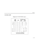
The arrows in Figure J-4 represent the direction of the signal. The pinouts assume that the 8-
conductor cable connecting the Server and the adapter block is a swapped cable. Both the transmit
and receive ground signals on the Server connector are wired to the signal ground on a DB9
adapter.
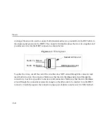
The information about crimping the RJ45 ground wires on page J-4 applies to the DB9 connector
as well.
Содержание EPS2-100
Страница 4: ...Declaration of Conformity Index ...
Страница 12: ......
Страница 25: ...TCP IP Configuration 4 9 4 Select the Add Port button and click Next ...
Страница 27: ...TCP IP Configuration 4 11 7 Select the manufacturer and printer type ...
Страница 28: ...TCP IP Configuration 4 12 8 Enter the queue name ...
Страница 30: ...TCP IP Configuration 4 14 10 Test the printer ...
Страница 40: ......
Страница 50: ......
Страница 58: ......
Страница 70: ......
Страница 75: ...Pinouts J 5 J 2 2 RJ45 to DB9 Figure J 4 RJ45 DTE DB9 Adapter ...
Страница 88: ...Updating Software K 12 ...
Страница 92: ...Specifications L 4 ...
Страница 108: ...Frequently used Commands M 16 ...
Страница 114: ......

