background image


2.2  IP Protection 

The 

IP Code

Ingress Protection Rating

, sometimes also interpreted as 

International 

Protection Rating

, classifies and rates the degree of protection provided against the 

intrusion (including body parts such as hands and fingers), dust, accidental contact, and 

water in 

mechanical casings

 and with electrical enclosures. It is published by the 

International Electrotechnical Commission (IEC) 


Solid particle protection 

The first digit indicates the level of protection that the enclosure provides against access 

to hazardous parts (e.g., electrical conductors, moving parts) and the ingress of solid 

foreign objects. 


Level 

Object size 

protected against 

Effective against 

— 

No protection against contact and ingress of objects 

>50 mm 

Any large surface of the body, such as the back of a 

hand, but no protection against deliberate contact 

with a body part 

>12.5 mm 

Fingers or similar objects 

>2.5 mm 

Tools, thick wires, etc. 

>1 mm 

Most wires, screws, etc. 

Dust protected 

Ingress of dust is not entirely prevented, but it must 

not enter in sufficient quantity to interfere with the 

satisfactory operation of the equipment; complete 

protection against contact 

Dust tight 

No ingress of dust; complete protection against 

contact 


Содержание IPES-3424DSFP-2P

Страница 1: ...IPES 3424DSFP 2P IES 3424DSFP 2P 24 10 100TX PoE 4 DualSpeed SFP Industrial L2 Switch w ITU G 8032 Ring User Manual Hardware Mar 2022...

Страница 2: ...y an STP network cable in demanding electrical environments Examples of demanding indoor environments are where the network cable is located in parallel with electrical mains supply cables or where la...

Страница 3: ...consent of Lantech Communications Global Inc Products offered may contain software which is proprietary to Lantech Communications Global Inc The offer or supply of these products and services does no...

Страница 4: ...occur in a particular installation If this equipment does cause harmful interference to radio or television reception which can be determined by turning the equipment off and on the user is encourage...

Страница 5: ...2 3 LED Indicators 7 Chapter 3 Hardware Installation 8 Hardware installation 8 3 1 Rack Mounting 10 3 2 Wiring the Power Inputs 12 3 3 Wiring the Fault Alarm Contact 14 3 4 Cabling 15 3 5 USB Dongle...

Страница 6: ...pter 1 Introduction Lantech I P ES 3424DSFP 2P is a high performance L2 managed industrial switch which provides L2 wire speed and advanced security function for network aggregation and backbone deplo...

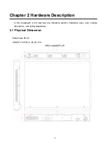
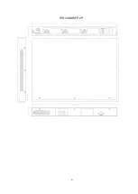
Страница 7: ...re Description In this paragraph it will describe the Industrial switch s hardware spec port cabling information and wiring installation 2 1 Physical Dimension Metal case IP 30 440 W x 325 D x 44 H mm...

Страница 8: ...3 IES 3424DSFP 2P...

Страница 9: ...t access to hazardous parts e g electrical conductors moving parts and the ingress of solid foreign objects Level Object size protected against Effective against 0 No protection against contact and in...
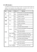
Страница 10: ...est duration 10 minutes Water equivalent to 3 mm rainfall per minute 3 Spraying water Water falling as a spray at any angle up to 60 from the vertical shall have no harmful effect Test duration 5 minu...

Страница 11: ...at least 1 m measured at bottom of device and at least 15 cm measured at top of device 8 Immersion beyond 1 m The equipment is suitable for continuous immersion in water under conditions which shall...

Страница 12: ...ff Power 1 is inactive PWR2 Green On Power 2 is active Off Power 2 is inactive FAULT Red On Power or port failure Off No failure RJ 45 Link Ack On A network device is detected Blinking The port is tra...

Страница 13: ...the Industrial switch in a 19 inch Rack 4 Power on the Industrial switch Please refer to the Wiring the Power Inputs section for knowing the information about how to wire the power The power LED on t...

Страница 14: ...9 7 When all connections are set and LED lights all show in normal the installation is complete...

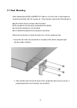
Страница 15: ...equipment rack brackets included with the switch Cross head screwdriver not provided Four standard equipment rack screws not provided Perform this procedure to install the switch in a 19 inch equipme...

Страница 16: ...11...

Страница 17: ...system power input 1 and 2 The power input module 2 is optional part 1 Insert DC power wires into the contacts and for power 1 or and 1 for power 2 2 Tighten the wire clamp screws for preventing the...

Страница 18: ...13 NOTE The wire gauge for the terminal block should be in the range between 12 24 AWG...

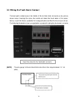
Страница 19: ...e switch will detect the fault status of the power failure or port link failure available for managed model and then forms an open circuit The following illustration shows an application example for w...

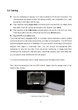
Страница 20: ...tor pluggable SFP is a compact optical transceiver used in optical communications for both telecommunication and data communications The SFP slots supporting Gigabit speed up to 1000Mbps They are used...

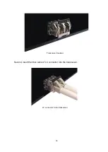
Страница 21: ...16 Transceiver Inserted Second insert the fiber cable of LC connector into the transceiver LC connector to the transceiver...

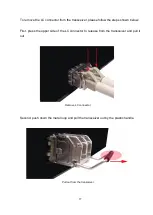
Страница 22: ...follow the steps shown below First press the upper side of the LC connector to release from the transceiver and pull it out Remove LC connector Second push down the metal loop and pull the transceive...

Страница 23: ...18 3 5 USB Dongle The USB slot is to backup and restore the setting of switch automatically by any USB dongle It doesn t need any configuration from web browser or other user interface...

Страница 24: ...cable which one end is DB9 female connector and the other end is DB9 male connector Attach the end of DB9 female connector to PC or terminal and the other end of DB9 male connector to the console port...

Страница 25: ...f the console port Baud Rate 115200 bps Data Bits 8 Parity none Stop Bit 1 Flow control None The settings of communication parameters Having finished the parameter settings click OK When the blank scr...

Страница 26: ...21 Console login interface Notice For web based management please refer to our Software Management Manual Please contact support lantechcom tw for more information...

Отзывы: