Lanoptik HE Series Скачать руководство пользователя страница 7

Chapter 5     Product Assembly Guide 

5.1 Camera Assembly 

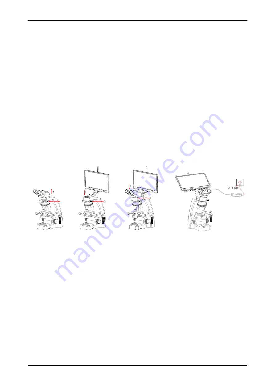
5.1.1 Assembly with biological microscope 

1. Take out the dust cover of the trinocular microscope, as shown in figure 5-5-1: 
1) Loosen the fixing screw of the dust cover of the trinocular microscope; 
2) Take out the dust cover of the microscope dovetail slot. 

2. Camera installation 
1) Place the camera to the dovetail slot of the microscope, as shown in figure 5-5-2; 
2) Tighten the fastening screw on the microscope dovetail slot and fix the camera on the microscope. 

3. Microscope eyepiece tube installation
1) The microscope eyepiece head is inserted into the master interface of camera, as shown in figure 5-5-3; 
2) Tighten the fastening screws of the camera; and fix the eyepiece head of microscope.

4. The adapter interface is inserted into the display power hole. Connect the adapter to 110-240V AC.

5.1.2 Disassembly the Camera 

Reverse the assembly sequence 

User's Manual | Microscope Camera HE Series

www.lanoptik.com

- 5 -

Fig. 5-5-1 

Fig. 5-5-3

Fig. 5-5-2 

Fig. 5-5-4

Содержание HE Series

Страница 1: ...All in one Embedded Smart Microscope Camera User s Manual www lanoptik com HE Series...

Страница 2: ...SCOPE CHAPTER 6 INSTRUCTIONS OF USE 6 1 SOFTWARE INSTALLATION 6 2 1 WiFi connection 6 2 2 HDMI connection 6 2 CAMERA CONNECTION 6 3 METHOD OF PARFOCALIZING 6 4 START TO USE CHAPTER 7 DISCLAIMER 1 1 2...

Страница 3: ...aces near heat source Please use and store in the following environment Operating temperature 0 40 Storage temperature 20 60 Operating Humidity 30 60 RH Storage Humidity 10 80 RH If any foreign matter...

Страница 4: ...t 10 GB available hard disk space 1000Mbps 100Mbps compatible with network cable interface 2 2 System Requirements for HDMI Work Mode The monitor has an HDMI TYPE A interface The display supports up t...

Страница 5: ...User s Manual Microscope Camera HE Series www lanoptik com 3 Mouse Keyboard Suite All in one Embedded Smart Camera 12V AC adapter 2 Hexagon key Chapter 3 Packing List...

Страница 6: ...als 11 Headset port For power supply 12 Reset hole Long press for 8 seconds to reset the camera 13 LED indicator Startup state the green light flashes when starting up until entering the system After...

Страница 7: ...igure 5 5 2 2 Tighten the fastening screw on the microscope dovetail slot and fix the camera on the microscope 3 Microscope eyepiece tube installation 1 The microscope eyepiece head is inserted into t...

Страница 8: ...scan icon in the App and scan the WiFi QR code on the top of camera to preview image 5 Please refer to User Manual of KoPa WiFi Lab for detailed operation Scan APP QR code to install APP Use the smar...

Страница 9: ...5 2 connect the camera with the display device with HDMI cable and turn on the HDMI display device 3 power the camera 4 Plug a mouse to the USB port 5 Long press the power switch on the camera for 3 s...

Страница 10: ...se carefully read the instructions disclaimers and safety instructions provided with this product before using it The company reserves the right to update the above documents Please operate the produc...

Страница 11: ...reet Lejia Road Baiyun District Guangzhou China 510400 Phone 86 20 3898 6017 Fax 86 20 3847 6076 Website http www lanoptik com Email info lanoptik com Specifications are subject to change without any...

Отзывы: