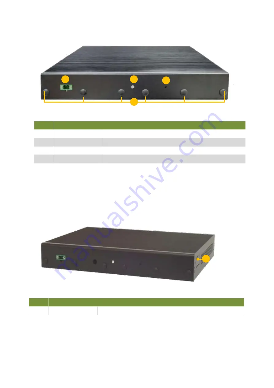
Lanner NCR-1510 Скачать руководство пользователя страница 15

Rear Panel


No. 

Description 

R1 

Power Switch 

1x Power Button   

R2 

Reset Button 

For software reset 

R3 

DC Jack 

1x DC Power Jack 

R4 

Antenna Port 

4x Reserved antenna port for Wi-Fi / LTE module 


Side Panel 


No. 

Description 

S1 

SIM Slot 

1x SIM Slot for accommodation of 2x Nano SIM   

R2 

R3

R1 

R4

S1 

Содержание NCR-1510

Страница 1: ...NCR 1510 User Manual Version 1 0 Date of Release 2020 06 23 Network Appliance Platform Hardware Platforms for Network Computing...

Страница 2: ...t font types and icons in order to make selected text more transparent and explicable to users This document contains the following conventions Font Conventions Example Convention Usage iptables F Mon...

Страница 3: ...port department Copyright and Trademarks This document is copyrighted 2020 by Lanner Electronics Inc All rights are reserved The original manufacturer reserves the right to make improvements to the pr...

Страница 4: ...73 Sec 2 Datong Rd Xizhi District New Taipei City 22184 Taiwan 221 173 7 T 886 2 8692 6060 F 886 2 8692 6101 E contact lannerinc com China Beijing L S Lancom Platform Tech Co Ltd Guodong LOFT 9 Layer...

Страница 5: ...d receiver Connect the equipment into an outlet on a circuit different from that to which the receiver is connected Consult the dealer or an experienced radio TV technician for help FCC Caution Any ch...

Страница 6: ...quipement dangereux Coupez compl tement l alimentation en teignant l alimentation et en d branchant le cordon d alimentation avant d installer ou de retirer un ch ssis ou de travailler proximit de sou...

Страница 7: ...ttent failures Be sure to follow ESD prevention procedures when removing and replacing components to avoid these problems Wear an ESD preventive wrist strap ensuring that it makes good skin contact If...

Страница 8: ...ay be greater than room ambient Therefore consideration should be given to installing the equipment in an environment compatible with the maximum ambient temperature Tma specified by the manufacturer...

Страница 9: ...s avoir teint l appareil Un c ble de mise la terre est requis et la zone reliant les sections du conducteur doit faire plus de 4 mm2 ou 10 AWG This equipment must be grounded The power cord for produc...

Страница 10: ...Front Panel 13 Rear Panel 14 Side Panel 15 Chapter 2 Motherboard Information 16 Block Diagram 16 Motherboard Layout 17 Chapter 3 Hardware Setup 18 Wall Mounting 18 DC Power Supply Installation 19 Appe...

Страница 11: ...nce for SD WAN uCPE or edge security gateway for enterprises Package Content Your package contains the following items 1x NCR 1510 Network Security Platform 1x Mini USB Console Cable 4x Rubber Foot Op...

Страница 12: ...e Power Button 1x Power Switch Console 1x Mini USB USB 2x USB 3 0 LCD Module N A Display N A Power Iinput 1x 2 pin terminal block Storage HDD SSD Support 1x 2 5 Internal Bay Onboard Slots 1x M 2 w LTE...

Страница 13: ...LED Indicator Power Status System Status Storage Activity F3 GbE Port 6x 10 100 1000Mbps Ethernet ports 4x 10 100 1000Mbps Ethernet ports F4 SFP Port 2x SFP Port with LED Indicator F5 USB Port 2x USB...

Страница 14: ...atus System Status Storage Activity F3 GbE Port 6x 10 100 1000Mbps Ethernet ports 4x 10 100 1000Mbps Ethernet ports F4 SFP Port 2x SFP Port with LED Indicator F5 USB Port 2x USB 3 0 Port SKU B C F6 SI...

Страница 15: ...1x Power Button R2 Reset Button For software reset R3 DC Jack 1x DC Power Jack R4 Antenna Port 4x Reserved antenna port for Wi Fi LTE module Side Panel No Description S1 SIM Slot 1x SIM Slot for accom...

Страница 16: ...CHAPTER 2 MOTHERBOARD INFORMATION Block Diagram The block diagram indicates how data flows among components on the motherboard Please refer to the following figure for your motherboard s layout design...

Страница 17: ...as a reference of the pin assignments and the internal connectors MPCIE1 MPCIE2 M 2 DIMM 2 DIMM 1 CON N1 CON1 PWR1 RST1 SIM1 SIM2 SIM3 80Port1 MIO1 JPCIESLOT1 CON1 J9 LAN6 LAN5 LAN4 LAN3 LAN2 LAN1 USB...

Страница 18: ...letely Also please wear ESD protection gloves when conducting the steps in this chapter Opening the Chassis Wall Mounting The system can be mounted on a flat surfaced wall Please take the following in...

Страница 19: ...les that match the four mounting holes on both brackets 3 Insert four anchoring bolts into the holes 4 Align the four mounting holes on the system s brackets with the four anchoring bolts you just ins...

Страница 20: ...d on top of the motherboard to install key parts and SSD drive First disconnect the Power Cable and USB 2 Pin cable Sku D E F before you do so Then remove the eight screws on the partition Unmount the...

Страница 21: ...below to install the DIMM memory modules 1 Locate the memory slots on the motherboard 2 Align the notch of the module with the socket key in the slot Tilt the end of the golden fingers down while car...

Страница 22: ...e notch of the module with the socket key in the slot Tilt the end of the golden fingers down while carefully inserting the card into the slot 3 Press vertically on the other end of the card until it...

Страница 23: ...rs down while carefully inserting the card into the slot 3 Press vertically on the other end of the card until it clicks into place Lock the module to the motherboard in the circle area Note NCA 1510...

Страница 24: ...motherboard 2 Locate the SSD drive slot on the partition 3 Connect the SATA cable to the hard disk 4 Mount the disk onto the empty partition with the provided disk screws Please mind the direction of...

Страница 25: ...the motherboard Note As you need to mount the partition on the motherboard please make sure you have installed all key parts you needs on the motherboard before you do so 6 Also remember to re connect...

Страница 26: ...slide in the PNG Module Installing the SIM Card 1 Slide the SIM card holder to the open position and then carefully lift it up 2 Insert the SIM card with the gold metal side facing outwards as shown...

Страница 27: ...vely attach fix the two cables to the connectors the red cable to the left Positive Pole and the black cable to the right Ground Pole 3 Connect the power cables to the power source This product is int...

Страница 28: ...running Off The system is powered off System Status This LED indicator is programmable You could program it to display the operating status of the behaviors described below Solid Green Defined by GPIO...

Страница 29: ...ense 5 The following conditions are excluded from this warranty Improper or inadequate maintenance by the customer Unauthorized modification misuse or reversed engineering of the product Operation out...

Страница 30: ...30 RMA Service Request Form When requesting RMA service please fill out the following form Without this form enclosed your RMA cannot be processed...

Отзывы: