background image


Network Computing Platforms


Appendix E: Terms and Conditions 

Warranty Policy 


1. All products are under warranty against defects in materials and workmanship for a period 

of one year from the date of purchase. 

2. The buyer will bear the return freight charges for goods returned for repair within the 

warranty period; whereas the manufacturer will bear the after service freight charges for goods 

returned to the user. 

3. The buyer will pay for repair (for replaced components plus service time) and transportation 

charges (both ways) for items after the expiration of the warranty period.   

4. If the RMA Service Request Form does not meet the stated requirement as listed on “RMA 

Service,” RMA goods will be returned at customer’s expense. 

5. 

The following conditions are excluded from this warranty:   

z

  Improper or inadequate maintenance by the 

• 

customer  

z


Unauthorized modification, misuse, or reversed 

• 

engineering of the product Operation 

outside of the environmental specifications for the product.


Requesting a RMA#   

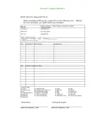
1. To obtain a RMA number, simply fill out and fax the “RMA Request Form” to your supplier. 

2. The customer is required to fill out the problem code  as listed. If your problem is not 

among the codes listed, please write the symptom description in the remarks box.   

3. Ship the defective unit(s) on freight prepaid terms. Use the original packing materials when 

possible.  

4. Mark the RMA# clearly on the box. 4.   

Note: 

Customer is responsible for shipping damage(s) resulting from inadequate/loose 

packing of the defective unit(s). All RMA# are valid for 30 days only; RMA goods received after 

the effective RMA# period will be rejected.


Содержание NCA-4210

Страница 1: ...Network Computing Platforms NCA 4210 User Manual Rev 1 2 September 26th 2016...

Страница 2: ...ectronics Inc Lanner Electronics Inc reserves the right to revise this document and to make changes in content from time to time without obligation on the part of Lanner Electronics Inc to provide not...

Страница 3: ...enclosure products FCC Class A Certification This equipment has been tested and found to comply with the limits for a Class A digital device pursuant to Part 15 of the FCC Rules These limits are desig...

Страница 4: ...t power is disconnected from a circuit always check the circuit LITHIUM BATTERY CAUTION Risk of explosion could occur if battery is replaced by an incorrect type Please dispose of used batteries accor...

Страница 5: ...ved due to uneven mechanical loading 4 Circuit Overloading Consideration should be given to the connection of the equipment to the supply circuit and the effect that overloading of the circuits might...

Страница 6: ...tre site propose une circulation d air adequate z Verifiez que le couvercle du chassis est bien fixe La conception du chassis permet a l air de refroidissement de bien circuler Un chassis ouvert laiss...

Страница 7: ...terre pour source d alimentation CC Proc dure de mise la terre pour source d alimentation CC Desserrez la vis du terminal de mise a la terre Branchez le cable de mise a la terre a la terre L appareil...

Страница 8: ...Setting and Connector Pin out 21 Jumper Settings 21 Connector Pin Assignments 23 Chapter 4 Hardware Setup 28 Installing the CPU 29 Installing the CPU Heat Sink and Fan Duct 32 Installing the System M...

Страница 9: ...65 Memory Configuration 66 PCH IO Configuration 67 Security 69 Boot 70 Save Exit 75 Appendix A Programming Watchdog Timer 78 Appendix B Setting up Console Redirection 79 Appendix C Programming Generat...

Страница 10: ...45 GbE LAN with 2 pairs of bypass Here is the summary of the key features z 6th generation Intel Core processor codenamed Skylake z PCH Intel H110 or C236 z 2 x DDR4 2400MHz ECC UDIMMs Up to 16GB each...

Страница 11: ...opper Bypass Console 1 x RJ 45 console port IPMI OPMA socket to support IPMI Networking Bypass 2 pairs of LAN bypass on RJ 45 ports Fan 2 x Cooling fans LCM 1x character type LCM LED POWER STATUS HDD...

Страница 12: ...unpack your package carefully and inspect all the following items 1 NCA 4210 Network Security Platform 1 power cable 1 Short Ear Rack mount kit with screws 1 Console cable 1 LAN Cable Grey Optional 1...

Страница 13: ...Network Computing Platforms NCS2 IQM201A NCS2 IXM407A AV ICE01 AV ICE02 AV ICE03 AV ICE04 AV CVE20000...

Страница 14: ...Network Computing Platforms Chapter 2 System Overview Mechanical Drawing NCA 4210A Unit mm...

Страница 15: ...Network Computing Platforms Mechanical Drawing NCA 4210B Unit mm...

Страница 16: ...Network Computing Platforms Block Diagram Note The 2 x 10G SFP ports are only available in model B...

Страница 17: ...s for system activities HDD status about storage devices such as HDD or SSD F2 LCM LCM with 4 x keypads F3 Console 1 x RJ 45 console port F4 USB 2 x USB 3 0 Type A ports in double stacked form F5 LAN...

Страница 18: ...ing Platforms Rear I Os R1 PCIe Expansion 1 x PCIe expansion slot optional R2 Fans 3 x cooling fans R3 Power switch 1 x power on off switch R4 power jack 1 x power jack for connection with power adapt...

Страница 19: ...ing Platforms Chapter 3 Board Layout Jumpers and Connectors on the Motherboard Notes SFP ports are in model B only FAN1 4 ATX1 DIO1 PCIESLOT1 JUSB1 mSATA SPIROM1 J1 DIMM1 2 ATX2 VGA1 LCM1 J5 OPMA1 COM...

Страница 20: ...Network Computing Platforms Jumpers and Connectors on the Motherboard cont d Notes TPM is optional J4 SATA2 3 CON1 JTPM1 J9 J7 80PORT1 J6 J8 J18...

Страница 21: ...software reset J1 PCIE Reversal Function the jumper to set PCIe normal or reversal behavior J2 PCIE X8 X4 Function select PCIe x4 or x8 mode Short Pins Description 1 2 Default Normal 2 3 Clear CMOS Sh...

Страница 22: ...3 PCIE 1X8 1X4 1X4 J5 POWER Button Function select ATX or AT power mode Short Pins Description 1 2 Default ATX MODE 2 3 AT MODE J9 GEN3 Bypass Flash Jumper select No Flash or Flash mode Short Pins Des...

Страница 23: ...double stacked type A connectors PIN NO DESCRIPTION PIN NO DESCRIPTION 1 V5USB 11 D2 2 USB3_RX1_N 12 D2 3 USB3_RX1_P 13 GND 4 GND 14 USB3_TX2 1 5 USB3_TX1_N 15 USB3_TX2 1 6 USB3_TX1_P 16 GND 7 GND 17...

Страница 24: ...To Send CTS J18 internal pin header for serial connection Pin number Pin signal In Out 1 Data Carrier Detect DCD 2 Data Set Ready DSR 3 Received Data RxD 4 Request To Send RTS 5 Transmitted Data TxD 6...

Страница 25: ...n 1 GND 2 P12V 3 FANIN 4 NC 5 FANOUT VGA Interface VGA1 Internal VGA Connector Pin No Description Pin No Description Pin No Description 1 CRT R 6 GND 11 DDC_DATA 2 GND 7 AHSYNC 12 DDC_CLK 3 CRT G 8 NC...

Страница 26: ...12V 3 Ground 4 VCC12 12V 5 Ground 6 VCC12 12V 7 Ground 8 VCC12 12V ATX2 24 pin ATX power supply connector Part reference ATX2 Pin Description Pin Description 1 3 3V 2 3 3V 3 3 3V 4 12V 5 Ground 6 Grou...

Страница 27: ...Network Computing Platforms 19 12V 20 5V 21 12V 22 5V 23 3 3V 24 Ground...

Страница 28: ...g procedures first WARNING z To reduce the risk of personal injury electric shock or damage to the equipment please remove all power sources z Please wear ESD protected gloves before conducting the fo...

Страница 29: ...top compartment Installing the CPU The motherboard supports 1 x 6th Generation Intel CPU codenamed Skylake with LGA1151 socket Please follow the steps below for installing the processor 1 Press the l...

Страница 30: ...Network Computing Platforms 2 Hold and drag the load lever outwards 3 Drag the load lever out of the latch...

Страница 31: ...Network Computing Platforms 4 Move the load lever as shown in the image below 5 Once the cover is opened you can install the CPU Then reverse the steps to securely lock the CPU socket...

Страница 32: ...upplied with a CPU heat sink and a fan duct as its thermal solution Please refer to the steps below 1 Prepare the supplied heat sink and place it on top of the CPU socket Make sure the 4 screws on the...

Страница 33: ...uct The fan duct will serve as the heat radiation bracket for the CPU and the motherboard 4 Fold the fan duct as shown in the image below 5 Place the folded fan duct on top of the heat sink Please mak...

Страница 34: ...Platforms 6 Remove the double sided tapes on the back as pointed by the two arrows in the diagram below 7 Fold and attach the tape of the right side of the fan duct to the aluminum bracket as shown i...

Страница 35: ...upports DDR4 ECC UDIMM up to 2 400MHz memory at max 16GB per socket Please follow the steps below to install the DIMM memory modules 1 Power off the system and locate the DDR DIMM slot 2 Pull open the...

Страница 36: ...HDDs or SSDs as data storage Please follow the steps below for installation Note the following steps are based on 2 x 2 5 SATA disk drives installation 1 Locate the disk drive tray at the corner of th...

Страница 37: ...disk drive as shown in the image below Apply 2 screws for each side of the disk drive 5 Place the tray with HDD SSD installed back to its original spot inside the system Remember to aim the two latch...

Страница 38: ...ve while using SATA 7 pin connector and SATA 4 pin connector for the motherboard Installing a mSATA Module The motherboard provides one mSATA slot Follow the procedures below for installing a mSATA ca...

Страница 39: ...The motherboard provides one OPMA socket which is used to install an IPMI card Please follow the steps below for instructions 1 Locate the OPMA socket 2 Insert an IPMI card into the socket and then pr...

Страница 40: ...lace a worn down fan please follow the steps below 1 Remove the screws circled below 2 Apply some force and pull the fan out of its original place as shown in the image below 3 Unplug the fan connecto...

Страница 41: ...bout compatible modules please refer to the Ordering Information and Optional Accessories sections or contact Lanner for more details 1 Rotate and loosen the two captive screws on the bezel of the mod...

Страница 42: ...Network Computing Platforms 3 Slide your Ethernet NIC module into the space until it is firmly attached 4 Secure the module with two captive screws on the bezel...

Страница 43: ...lect a setup screen for instance Main Advanced Chipset Boot Security and Save Exit select an item option on a setup screen Enter select an item option or enter a sub menu ESC exit the current screen t...

Страница 44: ...u may configure System Date and System Time BIOS Information BIOS Vendor displays BIOS vendor information BIOS Version displays BIOS version Build Date and Time displays the date and time the BIOS was...

Страница 45: ...anced setup screen Under this screen you may use to select an item you wish to configure Super IO Configuration Press Enter to access configuration sub menu for super IO chip parameters You may access...

Страница 46: ...entered Super I O configuration you may choose to configure Serial Port 1 or 2 or the Parallel port Super IO Configuration Serial Port 1 Configuration Press Enter to enable or disable the Serial Port...

Страница 47: ...ork Computing Platforms Super IO Configuration Serial Port 2 Configuration Once Serial Port 2 is accessed you may press Enter to enable or disable the Serial Port 2 COM Device setting is fixed as defa...

Страница 48: ...rms Parallel Port Configuration This option allows you to set parameters for parallel port LPT LPTE Once Parallel Port is accessed you may press Enter to enable or disable the Parallel Port Device set...

Страница 49: ...Network Computing Platforms HW Monitor This option allows you to view hardware health status...

Страница 50: ...rt Fan Configuration This option allows you to configure parameters about the cooling fans Press Enter to access the submenu CPU Smart Fan Mode Once Serial Port 2 is accessed you may press Enter to en...

Страница 51: ...Console Redirection This option allows you to configure parameters about serial port console redirection Press Enter to access the submenu Console Redirection select Enabled or Disable for COM port co...

Страница 52: ...ub menu COM Console Redirection Settings Terminal Type the emulation configuration Select VT100 VT100 VT UTF8 or ANSI VT100 ASCII character set VT100 extends VT100 to support color function keys VT UT...

Страница 53: ...0 19200 38400 57600 or 115200 for bits per second The Bps will determine serial port transmission speed The speed must be matched on the other side Long or noisy lines may require lower speeds Data Bi...

Страница 54: ...bit can be sent with the data bits to detect some transmission errors Select None Even Odd Mark or Space Stop Bits stop bits indicate the end of a serial data packet The standard is 1 stop bit Communi...

Страница 55: ...erflow When sending data if the receiving buffers are full a stop signal can be sent to stop the data flow You may select None or Hardware RTS CTS depending on the circumstances VT UTF8 Combo Key Supp...

Страница 56: ...ng Platforms Recorder Mode on this mode when Enabled only text will be sent This is to capture terminal data Putty KeyPad select Function Key and Key Pad on Putty You may select VT100 LINUX XTERMR6 SC...

Страница 57: ...ork Computing Platforms CPU Configuration This option allows you to configure CPU parameters Active Processor Cores number of cores to enable in each processor package The default is All for optimizat...

Страница 58: ...Bit an Intel hardware based protection against malicious code It will detect the memory in which a code can be executed or not When enabled it will prevent certain classes of malicious buffer overflo...

Страница 59: ...Network Computing Platforms SATA Configuration Press Enter to access items for SATA devices and settings SATA Mode Selection the selection to determine how SATA controllers operate...

Страница 60: ...Network Computing Platforms You may select AHCI or RAID mode Please be noted that there must be two SATA disk drives installed in order to enable RAID mode mSATA enable or disable the mSATA port...

Страница 61: ...Network Computing Platforms SATA1 enable or disable the SATA1 port SATA2 enable or disable the SATA2 port...

Страница 62: ...nfigure USB device Settings USB Devices displays USB devices Legacy USB Support this function enables or disables legacy USB support Auto option disables legacy support if no USB devices are connected...

Страница 63: ...Network Computing Platforms You may select Enabled Disabled or Auto...

Страница 64: ...Network Computing Platforms LAN Boot Select This option allows you to select one of the onboard LAN boot Press Enter to access the sub menu On Board LAN Boot the default is Disabled...

Страница 65: ...en Under this screen you may use to select System Agent SA Configuration or PCH IO Configuration System Agent SA Configuration displays and provides options to configure system agent SA parameters VT...

Страница 66: ...rk Computing Platforms Memory Configuration Memory Configuration provides memory configuration parameters Once accessed information about memory frequency total memory and DIMM 1 2 status will be disp...

Страница 67: ...ration provides PCH parameters Intel PCH RC Version displays Intel PCH RC version Intel PCH SKU Name displays PCH SKU name Intel PCH Rev ID displays Intel PCH revision ID Restore On Power Loss select...

Страница 68: ...Network Computing Platforms...

Страница 69: ...use to select an item you want to configure Administrator Password set administrator password Once set then this only limits access to Setup and is only asked for when entering Setup User Password set...

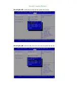
Страница 70: ...Network Computing Platforms Boot Use to select Boot setup screen Under this screen you may use to select an item you want to configure Boot mode select select boot mode LEGACY or UEFI...

Страница 71: ...Network Computing Platforms Boot Option 1 determine the device to be the first system boot device Boot Option 2 determine the device to be the second system boot device...

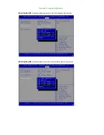
Страница 72: ...Network Computing Platforms Boot Option 3 determine the device to be the third system boot device USB Device BBS Priorities specifies the boot device priority sequence from available USB drives...

Страница 73: ...Network Computing Platforms Boot Option 1 set the device to be the first system boot device Boot Option 2 determine the device to be the second system boot device...

Страница 74: ...Network Computing Platforms Boot Option 3 determine the device to be the third system boot device Boot Option 4 determine the device to be the fourth system boot device...

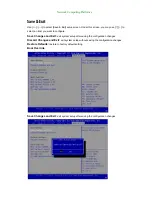
Страница 75: ...want to configure Save Changes and Exit exit system setup after saving the configuration changes Discard Changes and Exit exit system setup without saving the configuration changes Restore Defaults r...

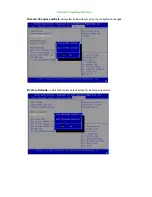
Страница 76: ...Network Computing Platforms Discard Changes and Exit exit system setup without saving the configuration changes Restore Defaults restore load factory default setting for all setup parameters...

Страница 77: ...Network Computing Platforms Boot Override You may select a device under Boot Override for this function...

Страница 78: ...on a counter that counts down from an initial value to zero The software selects the counter s initial value and periodically restarts it Should the counter reach zero before the software restarts it...

Страница 79: ...le port of the system and the other end to serial port of the Remote Client System 2 Configure the following settings in the BIOS Setup menu BIOS Advanced Remote Access Configuration Serial Port Mode...

Страница 80: ...s 1 Communication through SMBUS I2C 2 Independent bypass status control for each pair up to a total of 4 pairs 3 Lanner Bypass Modules can bypass systems Ethernet ports on a host system during three i...

Страница 81: ...wnload center and browse the download center and look for Lanner LAN Bypass Watchdog User Manual under the Accessories folder Fro a description of the physical LAN ports equipped with this function re...

Страница 82: ...See next section For Parallel Text based LCM Build To build program source code on Linux platform please use the following steps as a guideline 1 Extract the source file tar xzvf plcm_drv_v0XX tgz 0X...

Страница 83: ...ing off on the backlight of the LCM display Display Off turning off the LCM display Cursor Off On NOT showing showing the cursor on the LCM display Blinking off On turning off on the cursor blinking W...

Страница 84: ...ct Item 1 to set the starting line as either line 1 or line 2 Move cursor right select Item 2 to move the cursor to the right Move cursor left select Item 3 to move the cursor to the left Add a char s...

Страница 85: ...xample add to etc libvirt qemu yourvirtualmachine xml in linux KVM parallel type dev source path dev parport0 target port 0 parallel 3 Open a terminal in the Guest OS and then issue the following comm...

Страница 86: ...modprobe parport_pc modprobe ppdev 4 Check that whether the dev parport0 exists or not You may not find proper dev parport0 in the device list please reconfirm the setup of VMWare Player s setting pag...

Страница 87: ...customer s expense 5 The following conditions are excluded from this warranty z Improper or inadequate maintenance by the customer z Unauthorized modification misuse or reversed engineering of the pr...

Страница 88: ...Network Computing Platforms...

Отзывы: