ICS-I370 User Manual
36
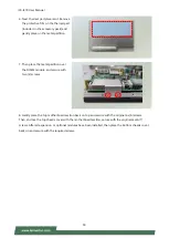
5. Next, thermal pad placement. Remove the
protective film on the thermal pad (included
in accessory pack) and gently place on the
larger square piece on the bottom chassis
cover (which once covered, will be placed
over LTE/5G module card).
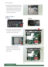
Front Panel
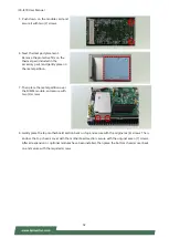
1. Locate the four (4) antenna hole placement
(A1, A2, A3, A4). Locate the four (4) IPEX
connectors on the 5G module card.
2. Connect the RF cables to the IPEX
connectors on the 5G module card and
screw the other end of the cables in the
antenna holes.
A1
A2
ㄉ
Top Panel
A3
ㄉ
A4
ㄉ
A1
A2
ㄉ
Содержание ICS-I370
Страница 13: ...ICS I370 User Manual 13...
Страница 26: ...ICS I370 User Manual 26 4 Lift the cover to remove...
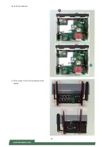
Страница 37: ...ICS I370 User Manual 37 3 Then screw on the four antennas to the system A3 A4...
Страница 45: ...ICS I370 User Manual 45...
Страница 47: ...ICS I370 User Manual 47...
Страница 59: ...ICS I370 User Manual 59 Socket 0 CPU Information...
Страница 65: ...ICS I370 User Manual 65...
Страница 70: ...ICS I370 User Manual 70...
Страница 71: ...ICS I370 User Manual 71 SATA Drives...


