background image

Chapter 3: Hardware Setup


To  access  some  components  and  perform  certain  service  procedures,  you  must  perform  the  following 
procedures first. 


Warning: 

To reduce the risk of personal injury, electric  shock,  or  damage  to  the  equipment, 

remove the power cord to remove power from the  server. The  front  panel  Power  On/Standby 
button  does not completely shut off system power.  Portions  of  the  power  supply  and  some 
internal  circuitry remain active until AC power is removed.


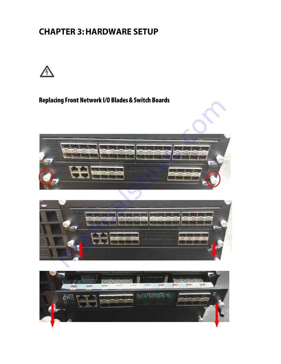
The  system  provides  a  total  of  six  externally  accessible  LAN  I/O  blades  and/or  switch  boards,  varied 
depending on ordering configurations (the system supports up to 2x switch boards and up to 5x LAN I/O 
blades). To replace a new blade/board, please follow the steps below. 
 

1.


Rotate and loosen the two captive screws at both ends. You may use a screwdriver to conduct this task. 


2.


Pull the two locks towards the directions as shown in the arrows of directions below. 


3.


Gently pull the board/blade out. 


Содержание HLM-1001

Страница 1: ...HLM 1001 User Manual Version 1 0 Date of Release 2018 09 26 Telecom Datacenter Appliances...

Страница 2: ...anual is intended to be accurate and reliable However the original manufacturer assumes no responsibility for its use nor for any infringements upon the rights of third parties that may result from su...

Страница 3: ...orking near power supplies Do not work alone if potentially hazardous conditions exist Never assume that power is disconnected from a circuit always check the circuit Risk of Explosion if Battery is r...

Страница 4: ...ieu fixe comme en laboratoire salle d ordinateurs ou salle de classe L quipement lectrique g n re de la chaleur La temp rature ambiante peut ne pas tre ad quate pour refroidir l quipement une temp rat...

Страница 5: ...Version Date Descriptions 1 0 2018 09 26 Official Release...

Страница 6: ...formation 7 System Specifications 7 I O Overview 8 Block Diagram 9 Motherboard Layout 10 Internal Jumper Connectors 11 Replacing Front Network I O Blades Switch Boards 15 Warranty Policy 16 RMA Servic...

Страница 7: ...ernet Network Interface blade for HTCA 6000 Series HLM 1001B 24 port 10GbE SFP Ethernet Network Interface blade for HTCA 6000 Series Model HLM 1001 Controller Intel XL710 Ethernet Controller Interface...

Страница 8: ...HLM 1001 User Manual No Description A 10GbE SFP Ports B PCIE 3 0 x8 Press fit connector B A...

Страница 9: ...Chapter 2 Motherboard Information The block diagram indicates how data flows among components on the motherboard Please refer to the following figure for your motherboard s layout design...

Страница 10: ...1001 User Manual The motherboard layout shows the connectors and jumpers on the board Refer to the following picture as a reference of the pin assignments and the internal connectors P1 J1 J2 CON2 CO...

Страница 11: ..._PE2ATP1 CPU1_PE2ATN2 F CPU1_PE3ATP0 GND CPU1_PE3BTN7 GND CPU1_PE2ATN1 GND G GND CPU1_PE3ARP2 GND CPU1_PE3ARP0 GND CPU1_PE2CRP9 H CPU1_PE3BTP5 CPU1_PE3ARN2 CPU1_PE3ARP1 CPU1_PE3ARN0 CPU1_PE2CRP8 CPU1_...

Страница 12: ...BRP6 GND PCIE_RESET L CPU1_PE2ARN3 CPU1_PE2BRN4 CPU1_PE2BRP5 CPU1_PE2BRN6 CPU1_PE2BRP7 WATCH_DOG M CPU1_PE2ARN3 GND CPU1_PE2BRN5 GND CPU1_PE2BRN7 GND N GND CPU1_PE1ATN3 GND CPU1_PE1BTP6 GND SMB_CH2_DA...

Страница 13: ...GND R GND NC GND CPU2_PE3CTP9 GND CPU2_PE3CTN11 S CPU2_PE1BTN4 NC CPU2_PE3CTP8 CPU2_PE3CTN9 CPU2_PE3CTP10 CPU2_PE3CTP11 T CPU2_PE1BTP4 GND CPU2_PE3CTN8 GND CPU2_PE3CTN10 GND 7 8 9 10 11 12 A GND CPU2_...

Страница 14: ...NC NC PCIE_CLK_P C NC GND NC GND D GND NC GND NC E NC NC NC NC F NC GND NC GND G GND NC GND NC H NC NC NC NC J NC GND NC GND K GND NC GND NC L NC NC NC NC M NC GND NC GND N GND NC GND NC O NC NC NC NC...

Страница 15: ...he power supply and some internal circuitry remain active until AC power is removed The system provides a total of six externally accessible LAN I O blades and or switch boards varied depending on ord...

Страница 16: ...e following conditions are excluded from this warranty Improper or inadequate maintenance by the customer Unauthorized modification misuse or reversed engineering of the product Operation outside of t...

Страница 17: ...Appendix Terms and Conditions 17 When requesting RMA service please fill out the following form Without this form enclosed your RMA cannot be processed...

Отзывы: